


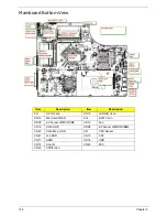


146
Chapter 4
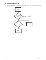
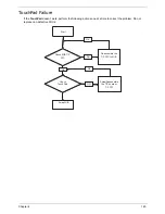
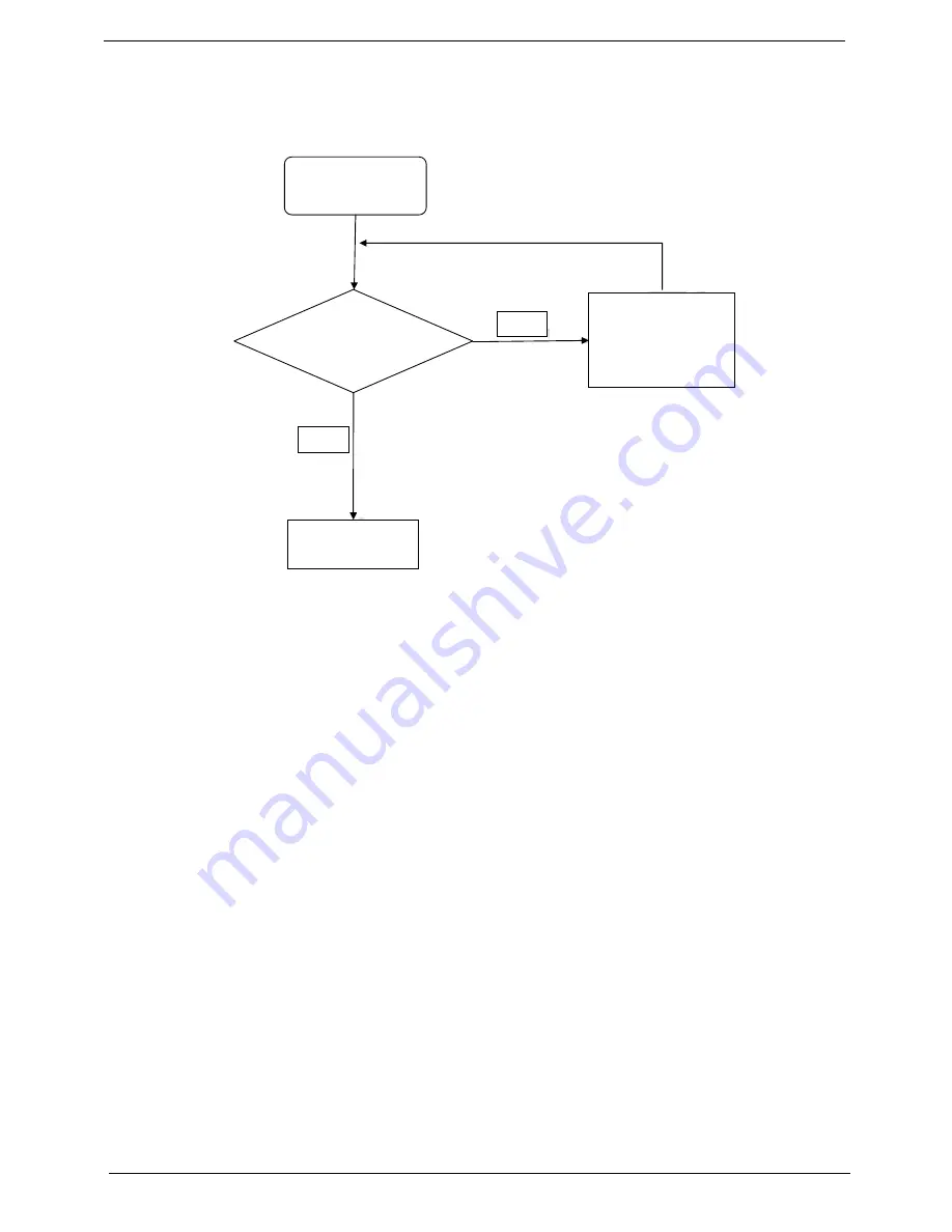
Internal Speaker Failure
If the internal
Speakers
fail, perform the following actions one at a time to correct the problem. Do not replace
non-defective FRUs:
Sound Problems
If sound problems are experienced, perform the following actions one at a time to correct the problem.
1.
Reboot the computer.
2.
Navigate to
Start
´
Control
Panel
´
System
and
Maintenance
´
System
´
Device
Manager
. Check
the Device Manager to determine that:
•
The device is properly installed.
•
There are no red Xs or yellow exclamation marks.
•
There are no device conflicts.
•
No hardware is listed under Other Devices.
3.
Roll back the audio driver to the previous version, if updated recently.
4.
Remove and reinstall the audio driver.
5.
Ensure that all volume controls are set mid range:
a.
Click the volume icon on the taskbar and drag the slider to 50. Ensure that the volume is not muted.
b.
Click Mixer to verify that other audio applications are set to 50 and not muted.
6.
Navigate to
Start
´
Control
Panel
´
Hardware
and
Sound
´
Sound
. Ensure that Speakers are selected
as the default audio device (green check mark).
NOTE:
If Speakers does not show, right-click on the
Playback
tab and select
Show
Disabled
Devices
(clear by default).
7.
Select Speakers and click
Configure
to start
Speaker
Setup
. Follow the onscreen prompts to configure
the speakers.
8.
Remove and recently installed hardware or software.
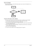
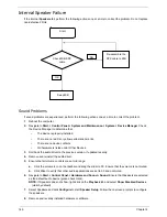
Start
Check M/B SPK
cable
Re-assemble the
SPK cable to M/B
NG
OK
Swap M/B
Содержание ASPIRE 7745
Страница 6: ...VI ...
Страница 10: ...X Table of Contents ...
Страница 40: ...30 Chapter 1 ...
Страница 56: ...46 Chapter 2 ...
Страница 68: ...58 Chapter 3 5 Pull the WLAN module out and away ...
Страница 73: ...Chapter 3 63 5 Remove the ODD bracket 6 Pry the ODD bezel off of the ODD module ...
Страница 83: ...Chapter 3 73 5 Detach the Bluetooth module cable from the module ...
Страница 91: ...Chapter 3 81 4 Lift the thermal module away from the main board ...
Страница 96: ...86 Chapter 3 4 Unlock and disconnect the switch board FFC ...
Страница 101: ...Chapter 3 91 4 Remove the bezel from the LCD module ...
Страница 108: ...98 Chapter 3 5 Pry the right antenna from the casing ...
Страница 111: ...Chapter 3 101 3 Lay the cables around the module edge ...
Страница 115: ...Chapter 3 105 10 Place the LVDS cable into cable guides ...
Страница 118: ...108 Chapter 3 4 Replace the two 2 bezel screws ...
Страница 121: ...Chapter 3 111 2 Using a flat bladed screw driver rotate the CPU locking screw 180 clockwise to secure the CPU in place ...
Страница 123: ...Chapter 3 113 Replacing the RTC Battery 1 Push the RTC battery into the cradle on the mainboard plus side up ...
Страница 129: ...Chapter 3 119 4 Connect the Bluetooth module cable to the main board ...
Страница 131: ...Chapter 3 121 4 Connect the LVDC cable 5 Lay the LVDS cable across the assembly as shown and press down firmly ...
Страница 136: ...126 Chapter 3 6 Connect and lock the Power board FFC ...
Страница 143: ...Chapter 3 133 4 Grasp the tab and slide the HDD firmly into the docking connector ...
Страница 145: ...Chapter 3 135 4 Push the ODD completely into the bay until flush with the lower cover ...
Страница 148: ...138 Chapter 3 ...
Страница 166: ...156 Chapter 4 ...
Страница 288: ...278 Appendix B ...
Страница 290: ...280 ...


