


24
Chapter 1
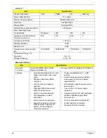
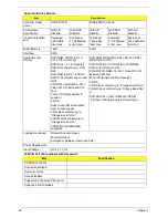
LAN Interface
Item
Specification
LAN Chipset
Atheros AR8151L
Package
48-pin QFN
Features
•
IEEE 802.3x compliant flow control support
•
IPv4 and IPv6 support
•
802.3u support
•
IEEE 802.1Q VLAN feature
•
Supports remote wake-up (including AMD Magic packet and MS Wake-up frame)
in both ACPI and APM Device and Technology Features
•
Embedded switching regulator
•
Supports 25 MHz external shared-clock source
•
256 byte memory (using eFuse) embedded on-chip
•
Small footprint 40-pin QFN (5 x 5 mm) package with dramatically improved
thermal and electrical characteristics over LQFP packaging
•
Co-layout with other Atheros 40-pin QFN 10/100 LOM Ethernet solution.
•
Integrated PHY for 10/100/1000 Mbps
•
IEEE 802.3 Auto-Negotiation support
•
IEEE 802.3ab PHY compliance and compatibility
•
Supports automatic MDI/MDIX functions
•
Su/- 100 ppm clock offset
•
IEEE 802.3az support Host Offloading Features
•
IP, TCP, and UDP checksum offload capabilities
•
Transmit TCP segmentation
•
IPv6 offload
•
IEEE 802.1Q VLAN support
•
Wake on LAN support
•
Green Ethernet feature support
•
Supports Energy Star 5.0
•
PCI Express base 1.1 compliant
•
Supports single, one-lane PCIE connection
Содержание ASPIRE 7745
Страница 6: ...VI ...
Страница 10: ...X Table of Contents ...
Страница 40: ...30 Chapter 1 ...
Страница 56: ...46 Chapter 2 ...
Страница 68: ...58 Chapter 3 5 Pull the WLAN module out and away ...
Страница 73: ...Chapter 3 63 5 Remove the ODD bracket 6 Pry the ODD bezel off of the ODD module ...
Страница 83: ...Chapter 3 73 5 Detach the Bluetooth module cable from the module ...
Страница 91: ...Chapter 3 81 4 Lift the thermal module away from the main board ...
Страница 96: ...86 Chapter 3 4 Unlock and disconnect the switch board FFC ...
Страница 101: ...Chapter 3 91 4 Remove the bezel from the LCD module ...
Страница 108: ...98 Chapter 3 5 Pry the right antenna from the casing ...
Страница 111: ...Chapter 3 101 3 Lay the cables around the module edge ...
Страница 115: ...Chapter 3 105 10 Place the LVDS cable into cable guides ...
Страница 118: ...108 Chapter 3 4 Replace the two 2 bezel screws ...
Страница 121: ...Chapter 3 111 2 Using a flat bladed screw driver rotate the CPU locking screw 180 clockwise to secure the CPU in place ...
Страница 123: ...Chapter 3 113 Replacing the RTC Battery 1 Push the RTC battery into the cradle on the mainboard plus side up ...
Страница 129: ...Chapter 3 119 4 Connect the Bluetooth module cable to the main board ...
Страница 131: ...Chapter 3 121 4 Connect the LVDC cable 5 Lay the LVDS cable across the assembly as shown and press down firmly ...
Страница 136: ...126 Chapter 3 6 Connect and lock the Power board FFC ...
Страница 143: ...Chapter 3 133 4 Grasp the tab and slide the HDD firmly into the docking connector ...
Страница 145: ...Chapter 3 135 4 Push the ODD completely into the bay until flush with the lower cover ...
Страница 148: ...138 Chapter 3 ...
Страница 166: ...156 Chapter 4 ...
Страница 288: ...278 Appendix B ...
Страница 290: ...280 ...


