


98
Chapter 3
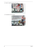
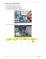
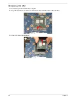
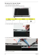
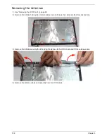
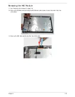
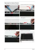
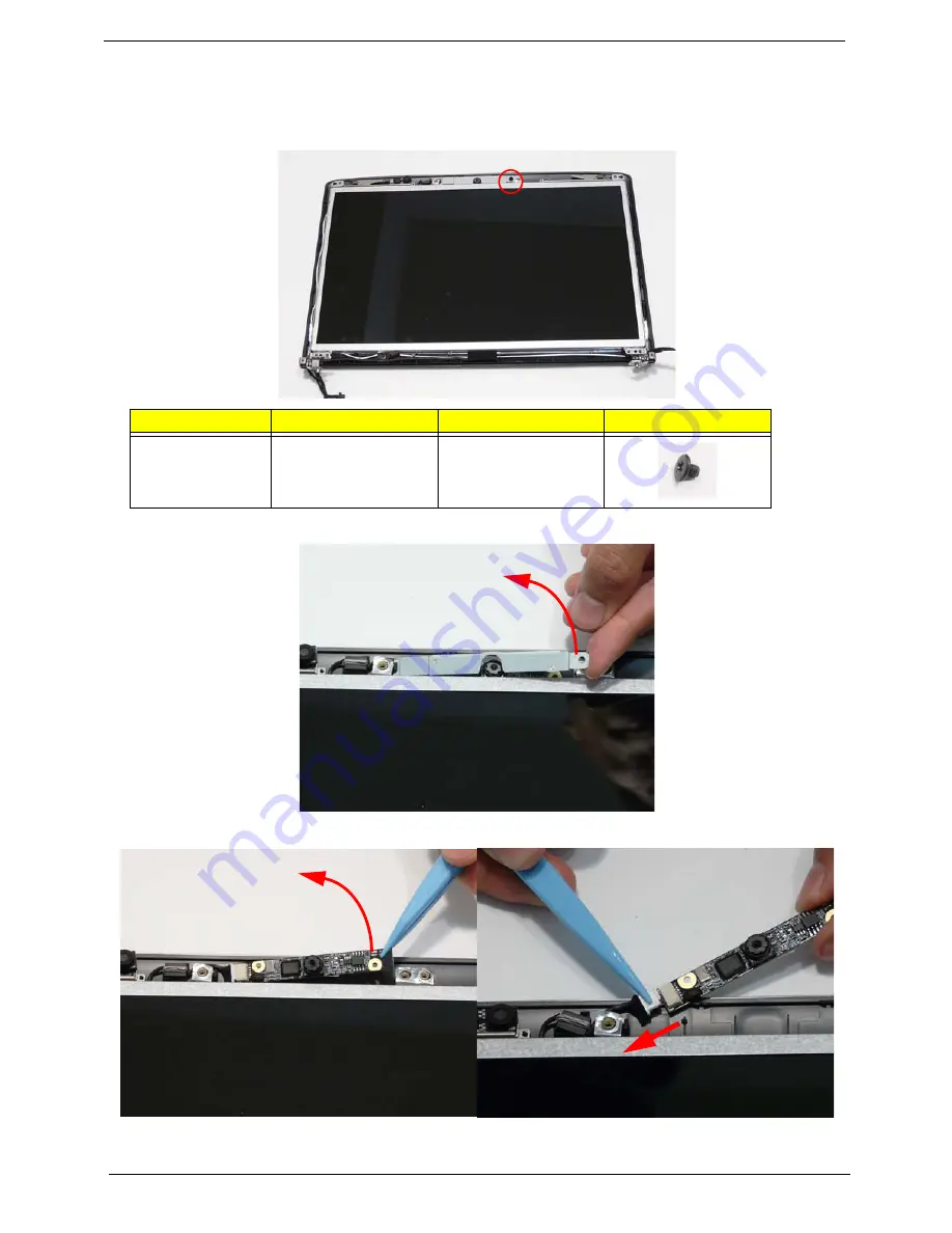
Removing the Camera Module
1.
See “Removing the LCD Bezel” on page 96.
2.
Remove the one (1) screw from the Camera Bracket as shown.
3.
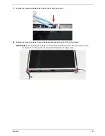
Lift the Camera Bracket, right side first, clear of the casing.
4.
Lift the Camera Module clear of the casing and disconnect the cable from the Module.
5.
Remove the Camera Module.
Step
Size
Quantity
Screw Type
Camera Module
M2.5*3
1
Содержание Aspire 4740G
Страница 6: ...VI ...
Страница 10: ...X Table of Contents ...
Страница 56: ...46 Chapter 2 ...
Страница 63: ...Chapter 3 53 5 Carefully open the HDD Cover ...
Страница 65: ...Chapter 3 55 5 Remove two 2 screws from the WLAN bracket and lift it clear of the device ...
Страница 90: ...80 Chapter 3 5 Remove the TouchPad Bracket from the Upper Cover ...
Страница 92: ...82 Chapter 3 Step Size Quantity Screw Type Media Board M2 5 3 2 ...
Страница 94: ...84 Chapter 3 5 Lift the FFC to detach the adhesive from the casing 6 Lift the USB Board clear of the casing ...
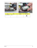
Страница 97: ...Chapter 3 87 Step Size Quantity Screw Type Bluetooth Module M2 5 3 1 ...
Страница 99: ...Chapter 3 89 7 Lift one edge of the mainboard as shown to remove it from the base ...
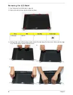
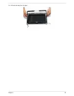
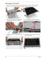
Страница 107: ...Chapter 3 97 4 Lift the bezel away from the panel ...
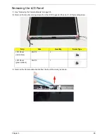
Страница 110: ...100 Chapter 3 4 Lift the LCD Panel out of the casing as shown ...
Страница 117: ...Chapter 3 107 13 Ensure that the securing pin is properly located ...
Страница 129: ...Chapter 3 119 ...
Страница 134: ...124 Chapter 3 4 Turn the computer over Replace the fifteen screws on the bottom panel ...
Страница 141: ...Chapter 3 131 4 Turn the computer over and replace the six 6 securing screws as shown ...
Страница 186: ...176 Chapter 6 ...
Страница 187: ...Chapter 6 177 ...
Страница 208: ...Appendix A 198 ...
Страница 214: ...204 Appendix B ...
Страница 216: ...206 Appendix C ...


