


48
Chapter 3
General Information
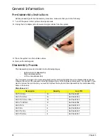
Pre-disassembly Instructions
Before proceeding with the disassembly procedure, make sure that you do the following:
1.
Turn off the power to the system and all peripherals.
2.
Unplug the AC adapter and all power and signal cables from the system.
3.
Place the system on a flat, stable surface.
4.
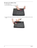
Remove the battery pack.
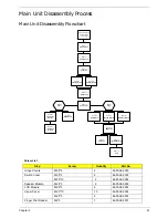
Disassembly Process
The disassembly process is divided into the following stages:
•
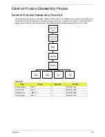
External module disassembly
•
Main unit disassembly
•
LCD module disassembly
The flowcharts provided in the succeeding disassembly sections illustrate the entire disassembly sequence.
Observe the order of the sequence to avoid damage to any of the hardware components. For example, if you
want to remove the main board, you must first remove the keyboard, then disassemble the inside assembly
frame in that order.
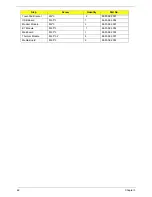
Main Screw List
Description
Quantity
Acer P/N
M2*3 ZK NL+
18
86.PAA02.001
M2.5*3 XK NL+
12
86.PAA02.002
M2.5*5 ZK NL+ CR3+
12
86.PAA02.003
M2.5*10 ZK NL+
12
86.PAA02.004
M2.5*4 ZK
5
86.PAA02.005
M3*3 NI+
4
86.PAA02.006
M2.5*3.2 NI+
4
86.PAA02.007
M2.5*5 NI NL+
8
86.PAA02.001
Содержание Aspire 4740G
Страница 6: ...VI ...
Страница 10: ...X Table of Contents ...
Страница 56: ...46 Chapter 2 ...
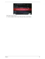
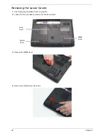
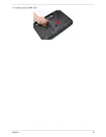
Страница 63: ...Chapter 3 53 5 Carefully open the HDD Cover ...
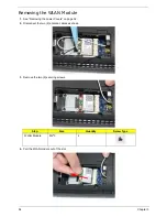
Страница 65: ...Chapter 3 55 5 Remove two 2 screws from the WLAN bracket and lift it clear of the device ...
Страница 90: ...80 Chapter 3 5 Remove the TouchPad Bracket from the Upper Cover ...
Страница 92: ...82 Chapter 3 Step Size Quantity Screw Type Media Board M2 5 3 2 ...
Страница 94: ...84 Chapter 3 5 Lift the FFC to detach the adhesive from the casing 6 Lift the USB Board clear of the casing ...
Страница 97: ...Chapter 3 87 Step Size Quantity Screw Type Bluetooth Module M2 5 3 1 ...
Страница 99: ...Chapter 3 89 7 Lift one edge of the mainboard as shown to remove it from the base ...
Страница 107: ...Chapter 3 97 4 Lift the bezel away from the panel ...
Страница 110: ...100 Chapter 3 4 Lift the LCD Panel out of the casing as shown ...
Страница 117: ...Chapter 3 107 13 Ensure that the securing pin is properly located ...
Страница 129: ...Chapter 3 119 ...
Страница 134: ...124 Chapter 3 4 Turn the computer over Replace the fifteen screws on the bottom panel ...
Страница 141: ...Chapter 3 131 4 Turn the computer over and replace the six 6 securing screws as shown ...
Страница 186: ...176 Chapter 6 ...
Страница 187: ...Chapter 6 177 ...
Страница 208: ...Appendix A 198 ...
Страница 214: ...204 Appendix B ...
Страница 216: ...206 Appendix C ...