


8
Chapter 1
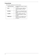
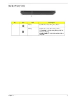
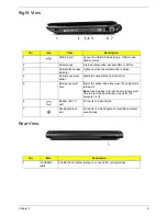
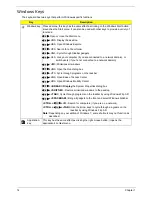
Left View
No.
Icon
Item
Description
1
DC in jack
Connects to an AC adapter
2
Ethernet (RJ-45)
port
Connects to an Ethernet 10/100/1000-based
network.
3
External display
(VGA) port
Connects to a display device
(e.g. external monitor, LCD projector).
4
USB 2.0
Connects to USB 2.0 devices.
5
HDMI
HDMI port
Supports high definition digital video
connections.
6
Line-in jack
Accepts audio line-in devices (e.g., audio CD
player, stereo walkman, mp3 player).
Microphone jack
Accepts inputs from external microphones.
Headphones/
speaker/line-out
jack with S/PDIF
support
Connects to audio line-out devices
(e.g., speakers, headphones).
7
Multi-in-1 card
reader
Accepts Secure Digital (SD), MultiMediaCard
(MMC), Memory Stick (MS), Memory Stick Pro
(MS PRO), and xD-Picture Card.
Note:
Push to remove/install the card. Only
one card can operate at any given time.
Содержание Aspire 4740G
Страница 6: ...VI ...
Страница 10: ...X Table of Contents ...
Страница 56: ...46 Chapter 2 ...
Страница 63: ...Chapter 3 53 5 Carefully open the HDD Cover ...
Страница 65: ...Chapter 3 55 5 Remove two 2 screws from the WLAN bracket and lift it clear of the device ...
Страница 90: ...80 Chapter 3 5 Remove the TouchPad Bracket from the Upper Cover ...
Страница 92: ...82 Chapter 3 Step Size Quantity Screw Type Media Board M2 5 3 2 ...
Страница 94: ...84 Chapter 3 5 Lift the FFC to detach the adhesive from the casing 6 Lift the USB Board clear of the casing ...
Страница 97: ...Chapter 3 87 Step Size Quantity Screw Type Bluetooth Module M2 5 3 1 ...
Страница 99: ...Chapter 3 89 7 Lift one edge of the mainboard as shown to remove it from the base ...
Страница 107: ...Chapter 3 97 4 Lift the bezel away from the panel ...
Страница 110: ...100 Chapter 3 4 Lift the LCD Panel out of the casing as shown ...
Страница 117: ...Chapter 3 107 13 Ensure that the securing pin is properly located ...
Страница 129: ...Chapter 3 119 ...
Страница 134: ...124 Chapter 3 4 Turn the computer over Replace the fifteen screws on the bottom panel ...
Страница 141: ...Chapter 3 131 4 Turn the computer over and replace the six 6 securing screws as shown ...
Страница 186: ...176 Chapter 6 ...
Страница 187: ...Chapter 6 177 ...
Страница 208: ...Appendix A 198 ...
Страница 214: ...204 Appendix B ...
Страница 216: ...206 Appendix C ...