
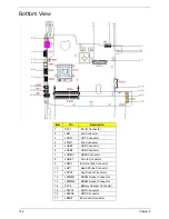


Chapter 2
163
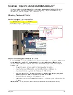
Clearing Password Check and BIOS Recovery
This section provide you the standard operating procedures of clearing password and BIOS recovery for
Aspire 4740 Series. Aspire 4740 Series provides one Hardware Open Gap on main board for clearing
password check, and one Hotkey for enabling BIOS Recovery.
Clearing Password Check
Hardware Open Gap Description
Steps for Clearing BIOS Password Check
If users set BIOS Password (Supervisor Password and/or User Password) for a security reason, BIOS will ask
the password during systems POST or when systems enter to BIOS Setup menu. However, once it is
necessary to bypass the password check, users need to short the HW Gap to clear the password by the
following steps:
•
Power Off a system, and remove HDD, AC and Battery from the machine.
•
Open the back cover of the machine, and find out the HW Gap on M/B as picture.
•
Use an electric conductivity tool to short the two points of the HW Gap.
•
Plug in AC, keep the short condition on the HW Gap, and press Power Button to power on the
system till BIOS POST finish. Then remove the tool from the HW Gap.
•
Restart system. Press F2 key to enter BIOS Setup menu.
•
If there is no Password request, BIOS Password is cleared. Otherwise, please follow the steps and
try again.
NOTE:
The steps are only for clearing BIOS Password (Supervisor Password and User Password).
Description
Location
Clear CMOS Jumper
Memory bay
Содержание Aspire 4740G
Страница 6: ...VI ...
Страница 10: ...X Table of Contents ...
Страница 56: ...46 Chapter 2 ...
Страница 63: ...Chapter 3 53 5 Carefully open the HDD Cover ...
Страница 65: ...Chapter 3 55 5 Remove two 2 screws from the WLAN bracket and lift it clear of the device ...
Страница 90: ...80 Chapter 3 5 Remove the TouchPad Bracket from the Upper Cover ...
Страница 92: ...82 Chapter 3 Step Size Quantity Screw Type Media Board M2 5 3 2 ...
Страница 94: ...84 Chapter 3 5 Lift the FFC to detach the adhesive from the casing 6 Lift the USB Board clear of the casing ...
Страница 97: ...Chapter 3 87 Step Size Quantity Screw Type Bluetooth Module M2 5 3 1 ...
Страница 99: ...Chapter 3 89 7 Lift one edge of the mainboard as shown to remove it from the base ...
Страница 107: ...Chapter 3 97 4 Lift the bezel away from the panel ...
Страница 110: ...100 Chapter 3 4 Lift the LCD Panel out of the casing as shown ...
Страница 117: ...Chapter 3 107 13 Ensure that the securing pin is properly located ...
Страница 129: ...Chapter 3 119 ...
Страница 134: ...124 Chapter 3 4 Turn the computer over Replace the fifteen screws on the bottom panel ...
Страница 141: ...Chapter 3 131 4 Turn the computer over and replace the six 6 securing screws as shown ...
Страница 186: ...176 Chapter 6 ...
Страница 187: ...Chapter 6 177 ...
Страница 208: ...Appendix A 198 ...
Страница 214: ...204 Appendix B ...
Страница 216: ...206 Appendix C ...