Chapter 3
43
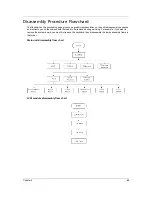
Disassembly Procedure Flowchard
The flowchart on the succeeding page gives you a graphic representation on the entire disassembly sequence
and instructs you on the components that need to be removed during servicing. For example, if you want to
remove the system board, you must first remove the keyboard, then disassemble the inside assembly frame in
that order.
Main unit disassembly flow chart
LCM module disassembly flow chart
Содержание Aspire 3810T Series
Страница 6: ...VI...
Страница 10: ...4 Chapter 1 System Block Diagram...
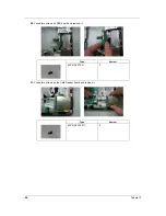
Страница 63: ...Chapter 3 57 34 Remove four steal parts to take off panel 35 Remove LCM cable on the back of panel...
Страница 86: ...80 Chapter 6 Aspire 3810T 3810TZ Exploded Diagram...
Страница 87: ...Chapter 6 81...
Страница 88: ...82 Chapter 6...
Страница 100: ...94 Chapter 6 SPEAKER Category Part Name and Description Acer Part No SPEAKER 23 PCR0N 002...

