


3-1
Machine Disassembly and Replacement
0
This chapter contains step-by-step procedures on how to disassemble the notebook
computer for maintenance and troubleshooting.
Cable paths and positioning may not represent the actual model. During the removal and
installation of the components, ensure all available cable channels and clips are used and
that the cables are replaced in the same position.
The screws for the different components vary in size. During the disassembly process, group
the screws with the corresponding components to avoid mismatch when putting back the
components.
The product previews seen in the disassembly procedures may not represent the final
product color or configuration.
Recommended Equipment
0
To disassemble the computer, the following tools are suggested:
Wrist grounding strap and conductive mat for preventing electrostatic discharge
Flat screwdriver
Philips screwdriver
Plastic flat screwdriver
Plastic tweezers
Cyanoacrylate glue
Replacement Requirements
0
NOTE:
NOTE
:
Cabling and components require adhesive to be applied during the replacement and
reassembly process.
Содержание Aspire 3750
Страница 1: ...Acer AS3750 AS3750G SERVICEGUIDE ...
Страница 4: ...iv ...
Страница 40: ...1 36 Hardware Specifications and Configurations ...
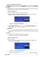
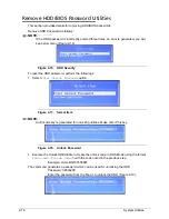
Страница 57: ...System Utilities 2 17 Figure 2 19 Unlock Password ...
Страница 75: ...3 15 Figure 3 24 Memory Module Figure 3 25 Memory Module ...
Страница 79: ...3 19 ...
Страница 81: ...3 21 Figure 3 33 TOP Case Figure 3 34 TOP Case 4 Pull touch padcableout of the slot and tear tape ...
Страница 83: ...3 23 Top case disassembly M2 5 3 5L 3 Table 3 1 Step Screw Quantity Screw Type ...
Страница 87: ...3 27 2 Disconnect the RTC BATTERY cable then take the battery away Figure 3 45 RTC BATTERY ...
Страница 94: ...3 34 Figure 3 58 LCD Module ...
Страница 98: ...3 38 Figure 3 65 LCD Panel ...
Страница 101: ...3 41 Figure 3 70 Hinge ...
Страница 103: ...3 43 Figure 3 73 CPU Module Figure 3 74 CPU Module ...
Страница 105: ...3 45 Figure 3 77 Main board Figure 3 78 Main board ...
Страница 108: ...3 48 Figure 3 83 Blue tooth Module Figure 3 84 Blue tooth Module ...
Страница 112: ...3 52 Figure 3 91 Top case Figure 3 92 Top case ...
Страница 115: ...3 55 Figure 3 97 Memory Figure 3 98 Memory ...
Страница 117: ...3 57 2 Secure 6 screws M2 5 6L and 2 screws M2 5 6L on bottom case Figure 3 101 LCD Module Figure 3 102 ODD Module ...
Страница 122: ...3 62 Figure 3 111 HDD Module Figure 3 112 HDD Module 4 Install HDD door secure 3 screws M2 5 4 5L ...
Страница 124: ...3 64 Figure 3 115 HDD Module Replacing Battery Module 0 1 Install the battery on bottom case Figure 3 116 Battery ...
Страница 163: ...FRU Field Replaceable Unit List 6 9 ...
Страница 192: ...6 38 FRU Field Replaceable Unit List ...
Страница 268: ...7 76 Model Definition and Configuration ...
Страница 272: ...8 4 Test Compatible Components ...