


System Utilities
2-7
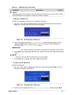
Setting a Password
0
Perform the following to set the user or supervisor password:
1.
Use the
and
keys to highlight the Set Supervisor Password parameter and press
Enter
key. The Set Supervisor Password box appears.
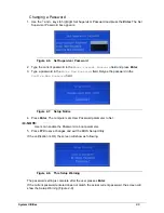
Figure 2-4.
Set Supervisor Password
2.
Type a new password in the
Enter New Password
field. Password length is not to
exceed 8 alphanumeric characters (A-Z, a-z, 0-9, not case sensitive). Retype the
password in the
Confirm New Password
field.
IMPORTANT
:
+
Use care when typing a password. Characters do not appear on the screen.
3.
Press
Enter
.
After setting the password, the computer sets the User Password parameter
to Set.
NOTE:
NOTE
:
Users can opt to enable the Password on boot parameter.
4.
Press
F10
to save changes and exit the BIOS Setup Utility.
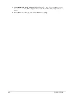
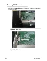
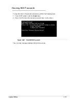
Removing a Password
0
Perform the following:
1.
Use the
and
keys to highlight Set Supervisor Password and press
Enter
. The Set
Supervisor Password box appears:
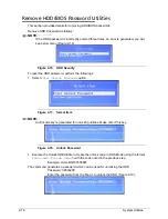
Figure 2-5.
Set Supervisor Password
2.
Type the current password in the
Enter Current Password
field and press
Enter
.
NOTE:
When prompted to enter a password, three attempts are allowed before the system halts. Resetting
the BIOS password may require the computer be returned to the dealer.
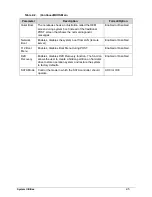
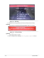
Table 2-3.
BIOS Security (Continued)
Parameter
Description
Option
Содержание Aspire 3750
Страница 1: ...Acer AS3750 AS3750G SERVICEGUIDE ...
Страница 4: ...iv ...
Страница 40: ...1 36 Hardware Specifications and Configurations ...
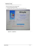
Страница 57: ...System Utilities 2 17 Figure 2 19 Unlock Password ...
Страница 75: ...3 15 Figure 3 24 Memory Module Figure 3 25 Memory Module ...
Страница 79: ...3 19 ...
Страница 81: ...3 21 Figure 3 33 TOP Case Figure 3 34 TOP Case 4 Pull touch padcableout of the slot and tear tape ...
Страница 83: ...3 23 Top case disassembly M2 5 3 5L 3 Table 3 1 Step Screw Quantity Screw Type ...
Страница 87: ...3 27 2 Disconnect the RTC BATTERY cable then take the battery away Figure 3 45 RTC BATTERY ...
Страница 94: ...3 34 Figure 3 58 LCD Module ...
Страница 98: ...3 38 Figure 3 65 LCD Panel ...
Страница 101: ...3 41 Figure 3 70 Hinge ...
Страница 103: ...3 43 Figure 3 73 CPU Module Figure 3 74 CPU Module ...
Страница 105: ...3 45 Figure 3 77 Main board Figure 3 78 Main board ...
Страница 108: ...3 48 Figure 3 83 Blue tooth Module Figure 3 84 Blue tooth Module ...
Страница 112: ...3 52 Figure 3 91 Top case Figure 3 92 Top case ...
Страница 115: ...3 55 Figure 3 97 Memory Figure 3 98 Memory ...
Страница 117: ...3 57 2 Secure 6 screws M2 5 6L and 2 screws M2 5 6L on bottom case Figure 3 101 LCD Module Figure 3 102 ODD Module ...
Страница 122: ...3 62 Figure 3 111 HDD Module Figure 3 112 HDD Module 4 Install HDD door secure 3 screws M2 5 4 5L ...
Страница 124: ...3 64 Figure 3 115 HDD Module Replacing Battery Module 0 1 Install the battery on bottom case Figure 3 116 Battery ...
Страница 163: ...FRU Field Replaceable Unit List 6 9 ...
Страница 192: ...6 38 FRU Field Replaceable Unit List ...
Страница 268: ...7 76 Model Definition and Configuration ...
Страница 272: ...8 4 Test Compatible Components ...