


1-20
Hardware Specifications and Configurations
System Board Major Chips
Processor
Processor Specifications
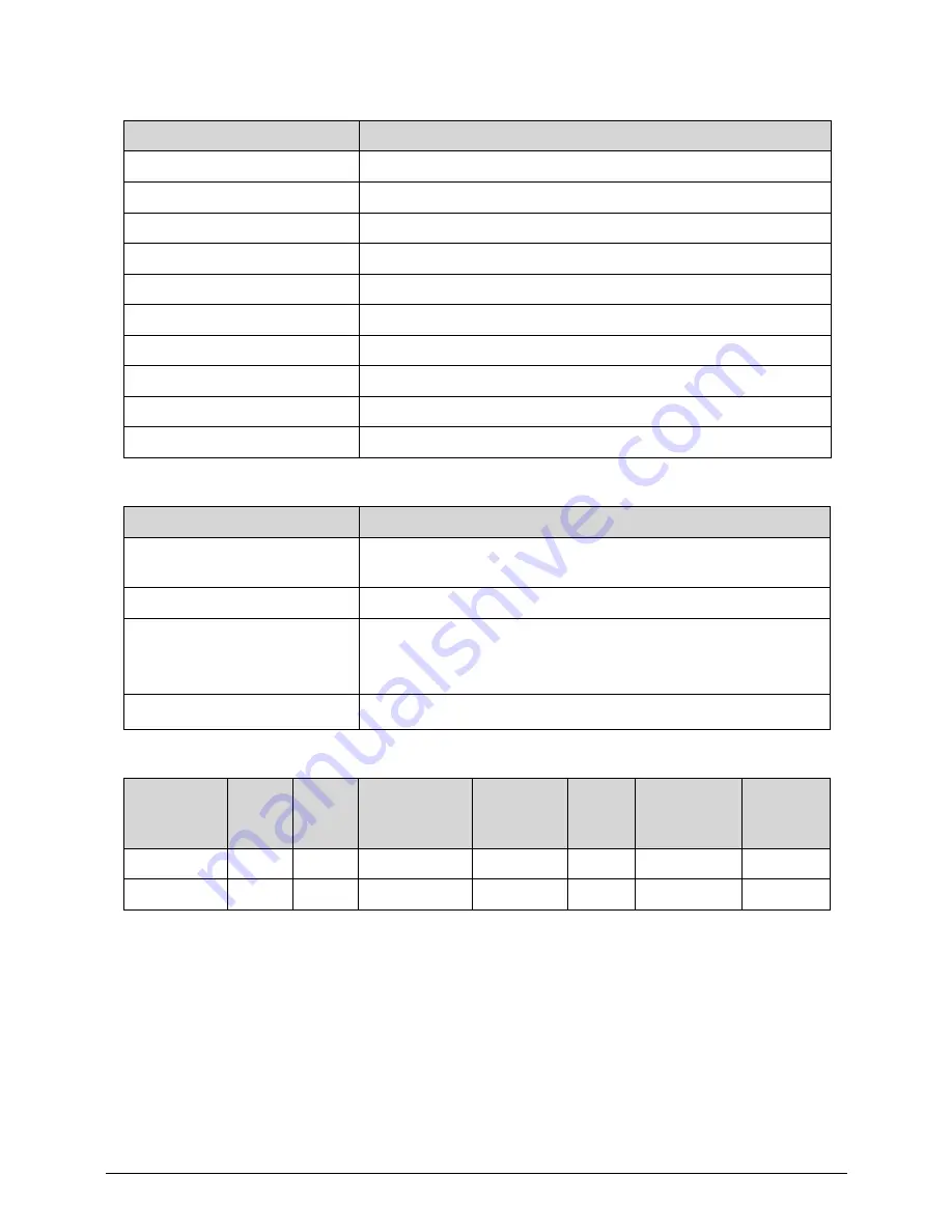
Item
Specification
Core logic
BD82HM65
VGA
CPU integrated / NVIDIA GT520M
LAN
Atheros AR8151
USB 3.0
RENESAS UPD720200AF1-DAP-A
Embedded Comtroller
NUVOTON NPCE794LA0DX
Bluetooth
FOXCONN T77H222.01 (Atheros AR3011)
Wireless
FOXCONN T77H167.07 (Atheros AR5B97)
PCMCIA
N/A
Audio codec
Realtek ALC271X-VB3-GR
Card reader
Realtek RTS5209-GR
Item
Specification
Central Processing Unit
(CPU) type
Intel
®
Core i5 Processor / Intel
®
Core i3 Processor
CPU package
rPGA988B
Core Logic
Two execution cores
Four Threads
Intel Smart Cache 3M
Chipset
Mobile Intel
®
HM65
Item
CPU
Speed
(
GHz
)
Cores
Bus
Speed(FSB/
DMI/QPI)
Mfg Tech
Cache
Size
Package
Core
Voltage
i5-2410M
2.3
2
20Gb/s
32 nm
3 MB
rPGA988B
1.1V
i3-2310M
2.1
2
20Gb/s
32 nm
3 MB
rPGA988B
1.1V
Содержание Aspire 3750
Страница 1: ...Acer AS3750 AS3750G SERVICEGUIDE ...
Страница 4: ...iv ...
Страница 40: ...1 36 Hardware Specifications and Configurations ...
Страница 57: ...System Utilities 2 17 Figure 2 19 Unlock Password ...
Страница 75: ...3 15 Figure 3 24 Memory Module Figure 3 25 Memory Module ...
Страница 79: ...3 19 ...
Страница 81: ...3 21 Figure 3 33 TOP Case Figure 3 34 TOP Case 4 Pull touch padcableout of the slot and tear tape ...
Страница 83: ...3 23 Top case disassembly M2 5 3 5L 3 Table 3 1 Step Screw Quantity Screw Type ...
Страница 87: ...3 27 2 Disconnect the RTC BATTERY cable then take the battery away Figure 3 45 RTC BATTERY ...
Страница 94: ...3 34 Figure 3 58 LCD Module ...
Страница 98: ...3 38 Figure 3 65 LCD Panel ...
Страница 101: ...3 41 Figure 3 70 Hinge ...
Страница 103: ...3 43 Figure 3 73 CPU Module Figure 3 74 CPU Module ...
Страница 105: ...3 45 Figure 3 77 Main board Figure 3 78 Main board ...
Страница 108: ...3 48 Figure 3 83 Blue tooth Module Figure 3 84 Blue tooth Module ...
Страница 112: ...3 52 Figure 3 91 Top case Figure 3 92 Top case ...
Страница 115: ...3 55 Figure 3 97 Memory Figure 3 98 Memory ...
Страница 117: ...3 57 2 Secure 6 screws M2 5 6L and 2 screws M2 5 6L on bottom case Figure 3 101 LCD Module Figure 3 102 ODD Module ...
Страница 122: ...3 62 Figure 3 111 HDD Module Figure 3 112 HDD Module 4 Install HDD door secure 3 screws M2 5 4 5L ...
Страница 124: ...3 64 Figure 3 115 HDD Module Replacing Battery Module 0 1 Install the battery on bottom case Figure 3 116 Battery ...
Страница 163: ...FRU Field Replaceable Unit List 6 9 ...
Страница 192: ...6 38 FRU Field Replaceable Unit List ...
Страница 268: ...7 76 Model Definition and Configuration ...
Страница 272: ...8 4 Test Compatible Components ...