


Hardware Specifications and Configurations
1-23
LAN Interface
Keyboard
BIOS ROM type
WINBOND W25Q32BVSSIG
MXIC MX25L3206EM2I-12G
BIOS ROM size
4MB
Features
INSYDE code base
Flash ROM 4 MB
Support Acer UI
Support multi-boot
Suspend to RAM (S3)/Disk (S4)
Support SMBIOS 2.6 ,PCI2.3.
DMI utility for BIOS serial number configurable/asset tag-
Support PXE
Support WinFlash
Wake on LAN from S3/S4
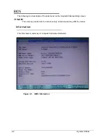
System information
HDD password
Refer to Acer BIOS specification.
Item
Specification
LAN Chipset
Atheros AR8151 PCI-E Gigabit Ethernet Controller
LAN connector type
RJ45
LAN connector location
RJ45 at the right side
Features
Supports 10/100/1000Mbps
Item
Specification
Type
Darfon/Sunrex/Chicony 86-/87-/91-key international language
support
Total number of keypads
86-/87-/91-key
Windows logo key
Yes
Internal & external keyboard
work simultaneously
Plug USB keyboard to the USB port directly: Yes
Features
Overlay numeric keypad
Support independent pgdn/pgup/pgup/home/end keys
Factory configurable different languages by OEM customer
Item
Specification
Содержание Aspire 3750
Страница 1: ...Acer AS3750 AS3750G SERVICEGUIDE ...
Страница 4: ...iv ...
Страница 40: ...1 36 Hardware Specifications and Configurations ...
Страница 57: ...System Utilities 2 17 Figure 2 19 Unlock Password ...
Страница 75: ...3 15 Figure 3 24 Memory Module Figure 3 25 Memory Module ...
Страница 79: ...3 19 ...
Страница 81: ...3 21 Figure 3 33 TOP Case Figure 3 34 TOP Case 4 Pull touch padcableout of the slot and tear tape ...
Страница 83: ...3 23 Top case disassembly M2 5 3 5L 3 Table 3 1 Step Screw Quantity Screw Type ...
Страница 87: ...3 27 2 Disconnect the RTC BATTERY cable then take the battery away Figure 3 45 RTC BATTERY ...
Страница 94: ...3 34 Figure 3 58 LCD Module ...
Страница 98: ...3 38 Figure 3 65 LCD Panel ...
Страница 101: ...3 41 Figure 3 70 Hinge ...
Страница 103: ...3 43 Figure 3 73 CPU Module Figure 3 74 CPU Module ...
Страница 105: ...3 45 Figure 3 77 Main board Figure 3 78 Main board ...
Страница 108: ...3 48 Figure 3 83 Blue tooth Module Figure 3 84 Blue tooth Module ...
Страница 112: ...3 52 Figure 3 91 Top case Figure 3 92 Top case ...
Страница 115: ...3 55 Figure 3 97 Memory Figure 3 98 Memory ...
Страница 117: ...3 57 2 Secure 6 screws M2 5 6L and 2 screws M2 5 6L on bottom case Figure 3 101 LCD Module Figure 3 102 ODD Module ...
Страница 122: ...3 62 Figure 3 111 HDD Module Figure 3 112 HDD Module 4 Install HDD door secure 3 screws M2 5 4 5L ...
Страница 124: ...3 64 Figure 3 115 HDD Module Replacing Battery Module 0 1 Install the battery on bottom case Figure 3 116 Battery ...
Страница 163: ...FRU Field Replaceable Unit List 6 9 ...
Страница 192: ...6 38 FRU Field Replaceable Unit List ...
Страница 268: ...7 76 Model Definition and Configuration ...
Страница 272: ...8 4 Test Compatible Components ...