


System Utilities
2-11
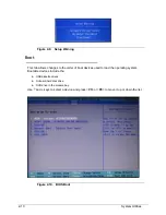
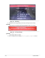
Exit
0
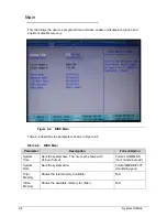
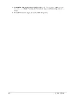
The Exit tab allows users to save or discard changes and quit the BIOS Utility.
Figure 2-11.
BIOS Exit
Table 2-4 describes the parameters in Figure 2-11.
Table 2-4.
Exit Parameters
Parameter
Description
Exit Saving Changes
Exit System Setup and save changes to the system.
Exit Discarding Changes
Exit utility without saving setup data to.
Load Setup Default
Load default values for all setup item.
Discard Changes
Load previous values all setup items.
Save Changes
Save setup data.
Содержание Aspire 3750
Страница 1: ...Acer AS3750 AS3750G SERVICEGUIDE ...
Страница 4: ...iv ...
Страница 40: ...1 36 Hardware Specifications and Configurations ...
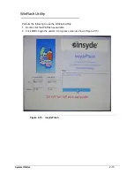
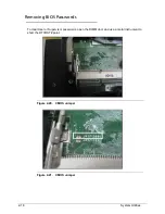
Страница 57: ...System Utilities 2 17 Figure 2 19 Unlock Password ...
Страница 75: ...3 15 Figure 3 24 Memory Module Figure 3 25 Memory Module ...
Страница 79: ...3 19 ...
Страница 81: ...3 21 Figure 3 33 TOP Case Figure 3 34 TOP Case 4 Pull touch padcableout of the slot and tear tape ...
Страница 83: ...3 23 Top case disassembly M2 5 3 5L 3 Table 3 1 Step Screw Quantity Screw Type ...
Страница 87: ...3 27 2 Disconnect the RTC BATTERY cable then take the battery away Figure 3 45 RTC BATTERY ...
Страница 94: ...3 34 Figure 3 58 LCD Module ...
Страница 98: ...3 38 Figure 3 65 LCD Panel ...
Страница 101: ...3 41 Figure 3 70 Hinge ...
Страница 103: ...3 43 Figure 3 73 CPU Module Figure 3 74 CPU Module ...
Страница 105: ...3 45 Figure 3 77 Main board Figure 3 78 Main board ...
Страница 108: ...3 48 Figure 3 83 Blue tooth Module Figure 3 84 Blue tooth Module ...
Страница 112: ...3 52 Figure 3 91 Top case Figure 3 92 Top case ...
Страница 115: ...3 55 Figure 3 97 Memory Figure 3 98 Memory ...
Страница 117: ...3 57 2 Secure 6 screws M2 5 6L and 2 screws M2 5 6L on bottom case Figure 3 101 LCD Module Figure 3 102 ODD Module ...
Страница 122: ...3 62 Figure 3 111 HDD Module Figure 3 112 HDD Module 4 Install HDD door secure 3 screws M2 5 4 5L ...
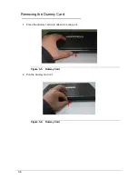
Страница 124: ...3 64 Figure 3 115 HDD Module Replacing Battery Module 0 1 Install the battery on bottom case Figure 3 116 Battery ...
Страница 163: ...FRU Field Replaceable Unit List 6 9 ...
Страница 192: ...6 38 FRU Field Replaceable Unit List ...
Страница 268: ...7 76 Model Definition and Configuration ...
Страница 272: ...8 4 Test Compatible Components ...