


2-6
System Utilities
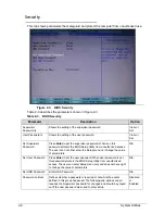
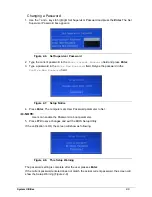
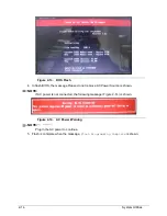
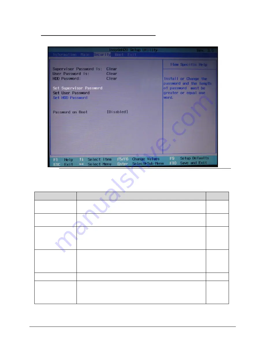
Security
0
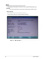
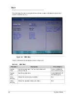
This tab shows parameters that safeguard and protect the computer from unauthorized use.
Figure 2-3.
BIOS Security
Table 2-3 describes the parameters shown in Figure 2-3.
Table 2-3.
BIOS Security
Parameter
Description
Option
Supervisor
Password Is
Shows the setting of the supervisor password
Clear or
Set
User Password Is
Shows the setting of the user password.
Clear or
Set
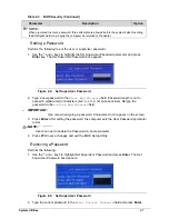
Set Supervisor
Password
Press
Enter
to set the supervisor password. When set, this
password protects the BIOS Setup Utility from unauthorized access.
The user can not either enter the Setup menu nor change the value
of parameters.
N/A
Set User Password
Press
Enter
to set the user password. When user password is set,
this password protects the BIOS Setup Utility from unauthorized
access. The user can enter Setup menu only and does not have right
to change the value of parameters.
N/A
Set HDD Password
Enter HDD Password.
N/A
Password on Boot
Defines whether a password is required or not while the events
defined in this group happened. The following sub-options are all
requires the Supervisor password for changes and should be grayed
out if the user password was used to enter setup.
Disabled
or
Enabled
Содержание Aspire 3750
Страница 1: ...Acer AS3750 AS3750G SERVICEGUIDE ...
Страница 4: ...iv ...
Страница 40: ...1 36 Hardware Specifications and Configurations ...
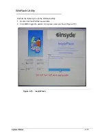
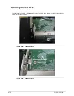
Страница 57: ...System Utilities 2 17 Figure 2 19 Unlock Password ...
Страница 75: ...3 15 Figure 3 24 Memory Module Figure 3 25 Memory Module ...
Страница 79: ...3 19 ...
Страница 81: ...3 21 Figure 3 33 TOP Case Figure 3 34 TOP Case 4 Pull touch padcableout of the slot and tear tape ...
Страница 83: ...3 23 Top case disassembly M2 5 3 5L 3 Table 3 1 Step Screw Quantity Screw Type ...
Страница 87: ...3 27 2 Disconnect the RTC BATTERY cable then take the battery away Figure 3 45 RTC BATTERY ...
Страница 94: ...3 34 Figure 3 58 LCD Module ...
Страница 98: ...3 38 Figure 3 65 LCD Panel ...
Страница 101: ...3 41 Figure 3 70 Hinge ...
Страница 103: ...3 43 Figure 3 73 CPU Module Figure 3 74 CPU Module ...
Страница 105: ...3 45 Figure 3 77 Main board Figure 3 78 Main board ...
Страница 108: ...3 48 Figure 3 83 Blue tooth Module Figure 3 84 Blue tooth Module ...
Страница 112: ...3 52 Figure 3 91 Top case Figure 3 92 Top case ...
Страница 115: ...3 55 Figure 3 97 Memory Figure 3 98 Memory ...
Страница 117: ...3 57 2 Secure 6 screws M2 5 6L and 2 screws M2 5 6L on bottom case Figure 3 101 LCD Module Figure 3 102 ODD Module ...
Страница 122: ...3 62 Figure 3 111 HDD Module Figure 3 112 HDD Module 4 Install HDD door secure 3 screws M2 5 4 5L ...
Страница 124: ...3 64 Figure 3 115 HDD Module Replacing Battery Module 0 1 Install the battery on bottom case Figure 3 116 Battery ...
Страница 163: ...FRU Field Replaceable Unit List 6 9 ...
Страница 192: ...6 38 FRU Field Replaceable Unit List ...
Страница 268: ...7 76 Model Definition and Configuration ...
Страница 272: ...8 4 Test Compatible Components ...