


5-4
Jumper and Connector Locations
Clearing Password Check and BIOS Recovery
0
This section provides procedures for:
Clearing Passwords
BIOS Recovery.
This Machine has one Hardware Open Gap on the main board for clearing password check
and one Hotkey for enabling BIOS Recovery.
Clearing Password Check
0
NOTE:
NOTE
:
The following procedure is only for clearing BIOS Password (Supervisor Password and
User Password).
Steps for Clearing BIOS Password Check
0
If users set BIOS Passwords (Supervisor Password and/or User Password) for a security
reason, BIOS will ask the password during systems POST or when system enters the BIOS
Setup menu. If it is necessary to bypass the password check, short the HW Gap to clear the
password by performing the following steps:
1.
Remove power from the system.
2.
Remove HDD, AC and Battery.
3.
Disconnect the RTC Battery (Figure 5-3).
Содержание Aspire 3750
Страница 1: ...Acer AS3750 AS3750G SERVICEGUIDE ...
Страница 4: ...iv ...
Страница 40: ...1 36 Hardware Specifications and Configurations ...
Страница 57: ...System Utilities 2 17 Figure 2 19 Unlock Password ...
Страница 75: ...3 15 Figure 3 24 Memory Module Figure 3 25 Memory Module ...
Страница 79: ...3 19 ...
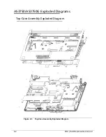
Страница 81: ...3 21 Figure 3 33 TOP Case Figure 3 34 TOP Case 4 Pull touch padcableout of the slot and tear tape ...
Страница 83: ...3 23 Top case disassembly M2 5 3 5L 3 Table 3 1 Step Screw Quantity Screw Type ...
Страница 87: ...3 27 2 Disconnect the RTC BATTERY cable then take the battery away Figure 3 45 RTC BATTERY ...
Страница 94: ...3 34 Figure 3 58 LCD Module ...
Страница 98: ...3 38 Figure 3 65 LCD Panel ...
Страница 101: ...3 41 Figure 3 70 Hinge ...
Страница 103: ...3 43 Figure 3 73 CPU Module Figure 3 74 CPU Module ...
Страница 105: ...3 45 Figure 3 77 Main board Figure 3 78 Main board ...
Страница 108: ...3 48 Figure 3 83 Blue tooth Module Figure 3 84 Blue tooth Module ...
Страница 112: ...3 52 Figure 3 91 Top case Figure 3 92 Top case ...
Страница 115: ...3 55 Figure 3 97 Memory Figure 3 98 Memory ...
Страница 117: ...3 57 2 Secure 6 screws M2 5 6L and 2 screws M2 5 6L on bottom case Figure 3 101 LCD Module Figure 3 102 ODD Module ...
Страница 122: ...3 62 Figure 3 111 HDD Module Figure 3 112 HDD Module 4 Install HDD door secure 3 screws M2 5 4 5L ...
Страница 124: ...3 64 Figure 3 115 HDD Module Replacing Battery Module 0 1 Install the battery on bottom case Figure 3 116 Battery ...
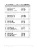
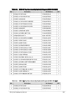
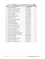
Страница 163: ...FRU Field Replaceable Unit List 6 9 ...
Страница 192: ...6 38 FRU Field Replaceable Unit List ...
Страница 268: ...7 76 Model Definition and Configuration ...
Страница 272: ...8 4 Test Compatible Components ...