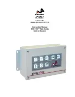
EVO 150 Controller
12
Troubleshooting
The following checklist has been provided to assist in the analysis and repair of potential trouble
situations with the EVO 150 system. If a situation occurs that is not described in this list, contact
AccuWeb for assistance.
Problem
Solution
The system will not work in Automatic, Manual, or Servo-
Center mode.
Check items 1, 2, 3, and 4 in
the table below.
When the system is in Automatic mode, the web guide steers
the web in the wrong direction.
Check item 6 in the table
below.
The system oscillates in Automatic mode even though web is
not being pulled through the machine.
Check items 7 and 8 in the
table below.
The system is unstable in Automatic mode while pulling web.
Check items 9, 10, 11, and 12
in the table below.
The actuator extends or retracts beyond the actuator’s end-of-
travel limits then jams.
Check items 13, 14, 15, 16,
17, 18, and 19 in the table
below.
The web guide or actuator hits a mechanical stop before
reaching the actuator's end-of-travel limit.
Check item 15 in the table
below.
The system will not work in Automatic mode but works
correctly in Manual and Servo-Center mode.
Check items 20, 21, and 22 in
the table below.
While in Automatic mode the web guide or actuator moves too
fast or slow in response to large changes in the position of the
edge of the web (such as a splice).
Check item 23 in the table
below.
While in Manual mode the web guide or actuator moves too
fast or too slow.
Check item 24 in the table
below.
It is necessary to perform a “Power-up Reset”:
If a power-up reset is
necessary, then check item 5
in the table below.
Item
Description / Repair Procedure
1
DC power.
If the LED near S1 is not lit or the switch pad LED’s are not lit,
check the DC power and repair if not connected.
2
No output from the PWM motor drive.
Connect a digital voltmeter to the
actuator motor leads at J6 terminals 1 and 2. Press the MANUAL button
and then press and hold the IN or OUT button. If there is no voltage but the
LED near S1 is lit, the PWM motor output has failed and the system must
be returned for repair.
3
Actuator failure.
If there is motor voltage present in the previous step but
the actuator does not move, the actuator motor or cable has failed.
Troubleshoot and repair as required, or return the equipment for repair.
4
INHIBIT input polarity is set wrong.
Set parameter 19 to the correct
value. Refer to page 21 for more information about setting controller
parameters.
Содержание EVO 150
Страница 1: ...P O Box 7816 Madison Wisconsin 53707 7816 Instruction Manual EVO 150 Web Guide Control System...
Страница 2: ......
Страница 6: ...EVO 150 Controller 4 EVO 150TM Web Guide Control System...
Страница 56: ...PointSource and WideArray Edge Detectors 54 PointSource and WideArray Edge Detectors...
Страница 62: ...AccuBeam 3 Digital Line Guide Sensor 60 AccuBeam 3 Digital Line Guide Sensor...
Страница 85: ...AccuWeb Linear Actuators 83 AccuWeb Linear Actuators...
Страница 90: ...Remote Station Guide Point Adjust 88 Remote Station Guide Point Adjust...
Страница 99: ...Remote Station Auxiliary 97 Remote Station Auxiliary...
Страница 104: ...Fieldbus Interface 102 Fieldbus Interface...
Страница 124: ......
Страница 125: ......
Страница 126: ......
Страница 127: ......
Страница 128: ......
Страница 129: ......
Страница 130: ......
Страница 131: ......
Страница 132: ......
Страница 133: ......
Страница 134: ......
Страница 135: ......
Страница 136: ......
Страница 137: ...NOTES...


