


78
1
Z E N ITH Z TG ( D/C T ) T-S E R I E S 16 0 0 -3 0 0 0 A
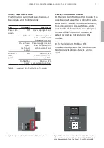
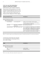
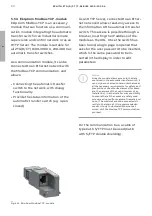
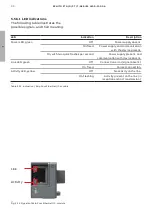
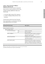
5.5.3.2 Termination resistor
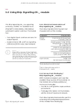
The modules provide the possibility to
insert a 120 Ω termination resistor on
the CAN bus, by setting the DIP-switches
Rterm (1 and 2) on the side of the mod-
ules, in position ON. This option must
be selected before the installation of
the modules. With the Ekip Com Devi-
ceNet - modules, the dip-switches 3 and
4 of the Rpol (polarization resistance),
are not used.
Rterm Rpol
120
Ω
on
on
off
off
ON IA
1 2 3 4
—
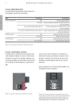
Fig. 5.18 Termination resistor; To enable the Rterm, the
dip-switches 1 and 2 must be positioned to ON. This option
must be selected before the installation of the module.
Notice
The termination resistors must never be in-
cluded in the nodes. The inclusion of this ca-
pability could easily lead to a network with im-
proper termination (impedance too high or
too low), potentially causing a failure. For ex-
ample the removal of a node, which includes a
termination resistor, could result in a network
failure. The termination resistors must not be
installed at the end of a branch (drop line),
only at the two ends of the main backbone
(trunk line).
Содержание Zenith ZTG T Series
Страница 2: ...2 1 ZENITH ZTG D CT T SERIES 1600 3000 A ...
Страница 6: ...6 1 ZENITH ZTG D CT T SERIES 1600 3000 A ...
Страница 10: ...10 1 ZENITH ZTG D CT T SERIES 1600 3000 A ...
Страница 38: ...38 1 ZENITH ZTG D CT T SERIES 1600 3000 A ...
Страница 60: ...60 ZENITH ZTG D CT T SERIES 1600 3000 A 1 LCD ...
Страница 104: ...104 1 ZENITH ZTG D CT T SERIES 1600 3000 A ...
Страница 116: ...2 116 ZENITH ZTG D CT T SERIES 1600 3000 A ...
Страница 120: ...2 120 ZENITH ZTG D CT T SERIES 1600 3000 A ...
Страница 123: ...123 1 OPER ATION MAINTENANCE AND INSTALL ATION GUIDE ...


