


Page 4
–10
2104349 rev. AD
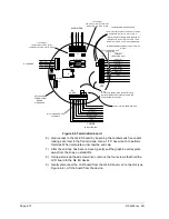
Figure 4
–5 Termination board
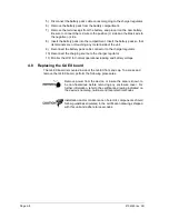
6) Gain access to the G4 EX board by loosening the countersunk hex socket
locking set screw in the front end cap. Use a 1/16” hex wrench to perform
this task. When completed, unscrew the end cap.
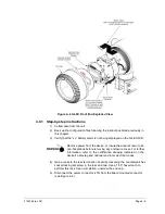
7) After the end cap has been removed, gently pull the graphic overlay plate
away from the snap on standoffs.
8) Using a small slot head screw driver, remove the four screws that hold the
LCD board to the G4 EX device.
9) Gently disconnect the LCD board from the G4 EX board, J2 connector (see
–6). Lift the board from the device.
S2
S3
3
J9
1
J11
3
1
1
COMM2
1
J20
J21
MMI
RTD
1
J2
5
6
9
J8
COMM1
1
J19
J16
PWR
J5
J6
J3
+ AI -
+ DI -
+ DO -
RTD OUT
SHIELD
RTD -
RTD +
RTD IN
-
+
TXD/TBUS(-)
RTS/TBUS(+)
RXD/RBUS(+)
CTS/RBUS(-)
COMM2 SW
GND
2
3
4
6
8
2
3
4
6
7
8
1
(-)
(+)
2
XFC
G4
6200EX
POWER/TERM
BOARD
2103344-XXX
I/O EXPANSION
ETHERNET
J7
USB CLIENT
J4
J12
3
1
J13
3
1
SECURITY
RESET
7
9
9
VBATT
OPERATE COMM2
5
5
RRTS COMM2
TXD/TBUS(-)
RTS/TBUS(+)
RXD/RBUS(+)
CTS/RBUS(-)
COMM2 SW
GND
VBATT
OPERATE COMM1
RRTS COMM1
J11 Terminates RS-485
on COMM2
J9 Terminates RS-485
on COMM1
J12 Jumper:
Jumper Pin1 to Pin 2 for AI
Jumper Pin 2 to Pin 3 for DOUT2
J13 Jumper:
Jumper Pin1 to Pin 2 for DOUT
Jumper Pin 2 to Pin 3 for AI2
5
4
3
2
1
(WHT)
(WHT)
(BLK)
(BLK)
(DRAIN)
COMM1
(RS-232/RS-485)
COMM2
(RS-232/RS-485)
RTD PROBE
A
I/
D
O
2
(+
)
A
I/
D
O
2
(-
)
D
I/
P
I(
+
)
D
I/
P
I
(-
)
D
O
/A
I2
(+
)
D
O
/A
I2
(-
)
AIs/DIs/DOs
Note:
Pinouts are shown to the outside for clarity,
but all of the Phoenix connectors are wired
and attached to the inside.
Jumpers for RS-485 Mode Only
If this is the last board on the bus, or if it is the
only board, jumper J9, Pin 1 to Pin 2.
There are a pair of jumper wires required for
RS-485 only: wire J19, Pin 9 to Pin 7 and
Wire Pin 8 to Pin 6 on the terminating board.
For all intermediate boards, Jumper J9, Pin 2
to Pin 3
Jumpers for RS-485 Mode Only
Содержание XSeries G4 6200
Страница 41: ...2104349 rev AD Page 1 27 Figure 1 22 Ethernet communication cable Figure 1 23 Ethernet connectivity diagram ...
Страница 42: ......
Страница 61: ...2104349 rev AD Page 2 19 Figure 2 18 G4 EX to UPS ...
Страница 62: ......
Страница 130: ......
Страница 163: ...2104349 rev AD Page 33 ...