background image

6

Dove:
I

= corrente di sovraccarico

I>

= corrente di soglia regolata

t

= tempo di intervento

α − β

= costanti che definiscono il tipo di caratteristica

K

= fattore di moltiplicazione del tempo di intervento

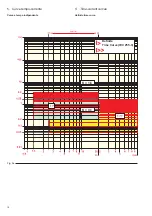
3.1.1. Scelta del valore di soglia (I>)

L'impostazione di I> viene effettuata agendo sui 6 dip switch
indicati in fig. 1 - rif. 1.
La somma dei valori selezionati rappresenta la frazione di In
corrispondente a I>.
Sono disponibili 32 valori di soglia, così definiti: 0,2 ... 1 x In con
passo 0,025 x In (non è possibile la predisposizione a 0,6 x In).
La protezione può essere esclusa posizionando il primo dip
switch sulla posizione OFF.
Nella seguente tabella si evidenziano le possibili
predisposizioni.

Where:
I

= overload current

I>

= set threshold current

t

= trip time

α − β

= constants which define the type of characteristic

K

= multiplication factor of the trip time

3.1.1. Selection of the threshold value (I>)

Setting the I> is carried out by acting on the 6 dip-switches
shown in fig. 1 - ref. 1.
The sum of the values selected represents the fraction of In
corresponding to I>.
32 threshold values are available, defined as follows: 0.2 ... 1
x In with steps of 0.025 x In (presetting to 0.6 x In is not possible).
The protection can be excluded by positioning the first dip-
switch on OFF.
The table below shows the possible settings.

3. Funzioni di protezione

Il PR512/P (50-51) realizza due funzioni di protezione (indi-
pendenti ed escludibili) contro sovraccarico e cortocircuito.

3.1. Protezione contro sovraccarico (51)

La funzione di protezione elabora il vero valore efficace (RMS)
per valori di corrente tra 0,2 e 2 x In. Per valori superiori la
protezione lavora sul valore di picco.
Sono disponibili 4 diverse famiglie di curve di protezione:
– Tempo indipendente regolabile (DT = Definite Time/tempo

indipendente)

– Tempo inverso (NI = Normally Inverse/tempo inverso)
– Tempo molto inverso (VI = Very Inverse/tempo molto inverso)
– Tempo estremamente inverso (EI = Extremely Inverse/tem-

po estremamente inverso).

Il valore di soglia di questa protezione viene indicato con I>,
mentre il relativo tempo d'intervento viene indicato con t>.
L'inizio della temporizzazione è segnalata dall'accensione
del led ALARM (fig. 1 - rif. 7) mentre l'avvenuta apertura
dell'interruttore è segnalata frontalmente dalla bandierina
magnetica I> I>> (fig. 1 - rif. 6) ruotata nella posizione di color
giallo.
Per ripristinare questa segnalazione è necessario premere il
pulsante FLAG RESET (fig. 1 - rif. 20) sul fronte dell'unità
garantendo una delle seguenti condizioni:
a) tensione ausiliaria 24 V cc presente (display acceso);
b) corrente circolante primaria maggiore di 0,2 x In (display

acceso con indicazione della corrente circolante);

c) applicazione del dispositivo TT2 al connettore TEST (fig.

1 - rif. 30) posto sul fronte dell'unità (accessorio a richiesta).

Per le protezioni a tempo indipendente, il tempo di intervento
delL'unità è dato dalla relazione:

t = K x 

β

Per le protezioni a tempo inverso, in accordo con le Norme IEC
255-4, il tempo d'intervento è dato dalla relazione:

β

t> = K x

[I/I>]

a

 - 1

3. Protection functions

The PR512/P (50-51) carries out two protection functions
(which are independent and can be excluded) against over-
load and short-circuit.

3.1. Protection against overload (51)

The protection function calculates the true effective value
(RMS) for current values between 0.2 and 2 x In. For higher
values, the protection works on the peak value.
There are 4 different families of protection curves available:
– Definite adjustable time (DT = Definite Time)
– Inverse time (NI = Normally Inverse time)
– Very inverse time (VI = Very Inverse time)
– Extremely inverse time (EI = Extremely Inverse time)
The threshold value of this protection is indicated by 1>,
whereas the relative trip time is indicated by t>.
The start of timing is signalled by the ALARM LED lighting up
(fig. 1 - ref. 7), whereas circuit-breaker opening is signalled on
the front by the magnetic flag I> I>> (fig. 1 - ref. 6) in the yellow
position.
To reset this signal, the FLAG RESET button must be pressed
(fig. 1 - ref. 20) on the front of the unit, thereby guaranteeing one
of the following conditions:
a) 24 V d.c. auxiliary voltage present (display lit);
b) primary circulating current higher than 0.2 x In (display lit

with indication of the current circulating);

c) application of the TT2 device to the TEST connector (fig. 1

- ref. 30) on the front of the unit (optional accessory).

For the definite time protections, the trip time of the unit is given
by the following relation:

t = K x 

β

For inverse time protections, in compliance with IEC 255-4
Standards, the trip time is given by the relation:

β

t> = K x

[I/I>]

a

 - 1

Содержание PR512

Страница 1: ...nzione di dialogo 36 23 Esempio di impostazione comunicazione seriale 38 24 Connessioni unit 38 25 Dati tecnici 39 26 Note e raccomandazioni 39 27 Messa in servizio 39 28 Controlli periodici 40 15 Ext...

Страница 2: ......

Страница 3: ...e di isolamentosull impianto For your safety Check that the installation room spaces segregations and ambient are suitable for the electrical and electronic apparatus Makesurethatalltheinstallation pu...

Страница 4: ...di collegarsi e di dialo gare con un sistema di gestione centralizzato SD View Introduction With regard to the electrical and construction characteristics and the overall dimensions of PR512 micropro...

Страница 5: ...24 Connessioni unit 38 25 Dati tecnici 39 26 Note e raccomandazioni 39 27 Messa in servizio 39 28 Controlli periodici 40 Index 1 PR512 P 50 51 unit Page 4 2 Phase current transformers 5 3 Protection f...

Страница 6: ...1 5 x In 1 PR512 P 50 51 unit Correct installation is of primary importance The manufacturer s instructions must be carefully studiedandfollowed All the installation operations must be carried out bys...

Страница 7: ...uare qualsi asi prova di isolamento sull impianto Nel caso in cui la corrente nominale dell interruttore sia minore della corrente nominale del trasformato re amperometrico esempio interruttore HD4 da...

Страница 8: ...avvenuta apertura dell interruttore segnalata frontalmente dalla bandierina magnetica I I fig 1 rif 6 ruotata nella posizione di color giallo Per ripristinare questa segnalazione necessario premere il...

Страница 9: ...to find t t K x 2 Inverse time curve NI a 0 02 0 14 see fig 9 b Set the dip switches as follows 0 14 Mathematical relation to find t t K x I I 0 02 1 where I represents the overload current and I the...

Страница 10: ...d Set the dip switches as follows 80 Mathematical relation to find t t K x I I 2 1 where I represents the overload current and I the set thresh old current Curva a tempo molto inverso VI a 1 13 5 ved...

Страница 11: ...orrente circolante primaria maggiore di 0 2x In display acceso con indicazione della corrente circolante c applicazione del dispositivo TT2 al connettore TEST fig 1 rif 30 posto sul fronte dell unit a...

Страница 12: ...ri di soglia e le predisposizioni sono qui sotto riportate OFF 2 5xI 3 5xI 4 5xI 5 5xI 7 5xI 8 5xI 9 5xI 10 5xI 12xI 13xI 14xI 15xI 17xI 18xI 19xI 20xI Fig 5 3 2 1 Selection of the threshold value I S...

Страница 13: ...switch 0 05 t 0 10 t 0 15 t 0 20 t 0 25 t 0 30 t 0 35 t 0 40 t 0 45 t 0 50 t 0 55 t 0 60 t 0 65 t 0 70 t 0 75 t 0 80 t 0 80 t 0 85 t 0 90 t 0 95 t 1 00 t 1 05 t 1 10 t 1 15 t 1 20 t 1 25 t 1 30 t 1 35...

Страница 14: ...gurazione riportata nella figura 7 realizza l imposta zione richiesta I I t OFF 0 0 0 0 0 05 0 0 0 0 2 5 1 2 5 9 5 0 8 0 4 0 2 0 1 0 05 Fig 7 3 2 3 Example of setting An example of setting the short c...

Страница 15: ...o Vaux 7 Contatto bistabile SRE b 2 Ingresso Vaux 8 Contatto bistabile P a 3 Non utilizzato 9 Contatto bistabile P b 4 Non utilizzato 10 Comando di apertura a distanza b 4 Unit connections Caption to...

Страница 16: ...rso o estre mamente inverso con l unit PR512 P questa funzione viene fornita solo a richiesta contro guasto a terra con tempo di intervento breve indipendente con lo sganciatore PR512 P questa funzion...

Страница 17: ...iliari sganciatore PR512 XZ Morsettiera nel quadro vedi nota B YC Sganciatore di chiusura dell interruttore YO1 Sganciatore di apertura dell interruttore YO3 Solenoide di apertura dell interruttore co...

Страница 18: ...4069 2x0 2 cod 07108 lungh max 30m input binari S33M e Q cavo schermato T14069 4x0 2 cod 07109 input binario S75I cavo schermato T14069 2x0 2 cod 07108 Notes A For the circuit breaker auxiliary circui...

Страница 19: ...Conductor connections Terminale o morsetto Terminal Presa e spina femmina e maschio Socket and plug female and male Trasformatore di corrente Current transformer Contatto di chiusura Make contact Con...

Страница 20: ...18 K 1 6 Definite Time Curve IEC 255 3 K 0 1 5 Curve tempo corrente Curva a tempo indipendente Fig 9a 5 Time current curves Definite time curve...

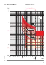
Страница 21: ...19 Curva a tempo normalmente inverso Fig 9b Normally inverse time curve...

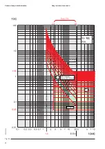
Страница 22: ...20 Fig 9c Curva a tempo molto inverso Very inverse time curve...

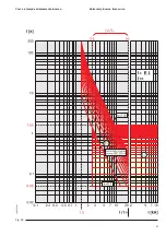
Страница 23: ...21 Fig 9d Curva a tempo estremamente inverso Extremely inverse time curve...

Страница 24: ...ssaggio Le dimensioni dell unit sono fig 10 altezza 160 mm larghezza 130 mm profondit 160 mm Le dimensioni indicate comprendono anche l ingombro dei connettori ma non quello di eventuali staffe di fis...

Страница 25: ...istance to mechanical stresses tests complying with the following standards Vibrations IEC 68 2 6 Impact IEC 68 2 27 Auxiliary voltage 24 V dc 20 30 V dc 10 Consumption 50 mA max in PR512 P configurat...

Страница 26: ...e alle seguenti funzioni di protezione omopolare 51N protezione da guasto omopolare di prima soglia 50N protezione da guasto omopolare di seconda soglia Signalling relay characteristics Maximum interr...

Страница 27: ...di intervento della protezione I 2 Dip switch per la predisposizione della temporizzazione K della protezione I 3 Dip switch per la predisposizione del tipo di curva DT NI VI EI della protezione I 4...

Страница 28: ...pplicazione del dispositivo TRIP TEST PR512 al connet tore TEST fig 11 rif 30 posto sul fronte dell unit acces sorio optional 15 External residual current transformer The value of the rated homopolar...

Страница 29: ...ndicates the fraction of In corresponding to Io 16 threshold values are available defined as follows 0 1 1xIn with steps of 0 05xIn settings to 0 3 0 55 and 0 8xIn are not possible The protection can...

Страница 30: ...cos definiti da 0 1 a 1 6 con passo 0 1 Nella seguente tabella si evidenziano i possibili valori K 1 3 K 1 4 K 1 5 K 1 6 K 0 1 K 0 2 K 0 3 K 0 4 K 0 5 K 0 6 K 0 7 K 0 8 K 0 9 K 1 0 K 1 1 K 1 2 Fig 13...

Страница 31: ...grafo 16 3 3 La configurazione riportata in figura 14 realizza l impostazione richiesta Io In 0 1 0 05 0 1 0 25 0 5 0 9 0 4 0 2 0 1 2 1 K OFF 0 0 0 0 0 1 0 0 0 0 0 Fig 14 16 3 4 Example of setting An...

Страница 32: ...isponibili 16 valori di soglia Le possibili predisposizioni sono riportate in tabella OFF 2 5xIo 3 5xIo 4 5xIo 5 5xIo 7 5xIo 8 5xIo 9 5xIo 10 5xIo 12xIo 13xIo 14xIo 15xIo 17xIo 18xIo 19xIo 20xIo Fig 1...

Страница 33: ...16 0 05 to 0 10 to 0 15 to 0 20 to 0 25 to 0 30 to 0 35 to 0 40 to 0 45 to 0 50 to 0 55 to 0 60 to 0 65 to 0 70 to 0 75 to 0 80 to 0 80 to 0 85 to 0 90 to 0 95 to 1 00 to 1 05 to 1 10 to 1 15 to 1 20...

Страница 34: ...o 10 Comando di apertura a distanza b Fig 18 Io Io OFF 0 0 0 0 0 05 0 0 0 0 2 5 1 2 5 9 5 0 8 0 4 0 2 0 1 0 05 INT 1 2 3 4 5 6 7 8 XK1 1 2 1 2 3 4 XK3 XK2 1 2 3 4 6 7 8 9 10 XK5 to Tor EXT 16 4 3 Exam...

Страница 35: ...zioni ambientali cap 10 Compatibilit elettromagnetica cap 11 Dati tecnici cap 12 Note e raccomandazioni cap 13 18 Other information Further information can be found in the previous chapters as they al...

Страница 36: ...lizzare le funzioni sopra citate necessario fornire all unit una alimentazione ausiliaria V aux compresa tra 24 Vc c 20 e 30 Vc c 10 Per le misure di corrente vale quanto riportato nel cap 1 Apart fro...

Страница 37: ...izione della velocit della trasmis sione seriale baud rate 26 Dip switch per la predisposizione indirizzo dell unit 27 Dip switch predisposizione calibro trasformatori amperometrici 28 Tappo copri dip...

Страница 38: ...y means of these inputs the signals regarding the state of the circuit breaker can be acquired In particular the following are available a input to acquire the state of circuit breaker OPEN b input to...

Страница 39: ...tch posti sul fronte dell unit o l impostazione elettronica ELECTR operata mediante siste ma centralizzato The serial interface used complies with IEC RS485 Standard and consequently the connections m...

Страница 40: ...7 8 XK1 1 2 1 2 3 4 XK3 XK2 XK5 1 2 3 4 6 7 8 9 10 XK6 1 2 3 4 XK4 1 2 3 4 6 7 8 9 10 24 Unit connections Caption to the unit connections with reference to fig 22 and relative descriptions XK1 1 Start...

Страница 41: ...ualifica suffi ciente e una conoscenza adeguata della apparec chiatura Scollegare l unit PR512 prima di effettuare qualsiasi prova di isolamento sull impianto Prima della messa in servizio necessario...

Страница 42: ...I e I Per effettuare l autodiagnosi della carica della batteria e del corretto funzionamento del TT2 porre il Dip Switch 1 in posizione A premere il pulsante CHECK e verificare l accen sione del LED S...

Страница 43: ......

Страница 44: ...D 14542 Glindow Phone 49 0 2102 12 1230 Fax 49 0 2102 12 1916 E mail calor info de abb com www abb com Dati e immagini non sono impegnativi In funzione dello sviluppo tecnico e dei prodotti ci riserv...

Отзывы: