25
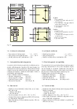
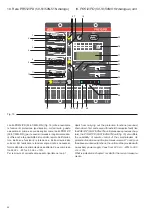
Caption
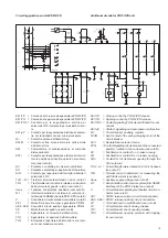
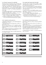
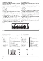
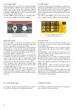
1 Dip-switch for setting the trip threshold of protection I>
2 Dip-switch for setting the time-delay K of protection I>
3 Dip-switch for setting the type of curve (DT, NI, VI, EI) of
protection I>
4 Dip-switch for setting the trip threshold of protection I>
5 Dip-switch for setting the trip time t>> of protection I>>
6 Bistable magnetic flag indicating protection I> or I>> tripped
7 LED indicating time-delay elapsing protection I> or I>>
8 Dip-switch for setting the tripthreshold of protection Io>
9 Dip-switch for setting the delay K of protection Io>
10 Dip-switch for setting the type of curve (DT, NI, VI, EI) of
protection Io>
11 Dip-switch for setting the trip threshold of protection Io>>
12 Dip-switch for setting the trip time to>> of protection Io>>
13 Dip-switch for setting the type of homopolar toroidal trans-
former (internal/external)
14 Bistable magnetic flag indicating protection Io> or Io>> tripped
15 LED indicating time-delay elapsing protection Io> or Io>>
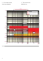
16 Time-current relation in conformity with IEC 255-4
17 Display showing the phase current with the highest load
18 Bistable magnetic flag signalling remote opening of the circuit-
breaker
19 RESET pushbutton of the microprocessor and bistable relays
signalling SRE and µPFAULT
20 Reset pushbutton for bistable magnetic flags (refs. 6, 14, 18)
21 LED indicating microprocessor fault (µP FAULT)
27 Dip- switch for setting rated current of current transformers
28 Dip-switch and CT “In” setting plate cover
29 Unit serial number
30 TEST connector.
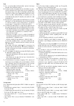
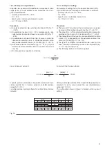
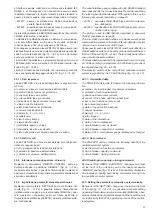
The homopolar current is calculated as the vectorial sum of the
three phase currents. This sum is obtained by means of the
toroidal current transformer inside the unit or by means of an
external residual current toroidal transformer (to be provided
by the customer) connected to inputs 7 and 8 of XK1 (see chap.
17).
Protection against earth fault is therefore possible if at least 3
phase CTs, or 2 phase CTs + external toroidal transformer are
connected to the unit.
When the unit is self-powered, the Io> and Io>> protection
functions are only activated if the primary current exceeds the
value of 0.2 x In, where In is the rated current of the phase CTs
To obtain higher performances, the unit must be provided with
an auxiliary power supply V aux = 24 V d.c.
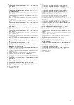
Legenda
1 Dip-switch per la predisposizione della soglia di intervento della
protezione I>
2 Dip-switch per la predisposizione della temporizzazione K della
protezione I>
3 Dip-switch per la predisposizione del tipo di curva (DT, NI, VI,
EI) della protezione I>
4 Dip-switch per la predisposizione della soglia di intervento della
protezione I>
5 Dip-switch per la predisposizione del tempo di intervento t>>
della protezione I>>
6 Bandierina magnetica bistabile di segnalazione protezione I> o
I>> intervenuta
7 Led di segnalazione temporizzazione in corso protezioni I> o
I>>
8 Dip-switch per la predisposizione della soglia di intervento della
protezione Io>
9 Dip-switch per la predisposizione della temporizzazione K della
protezione Io>
10 Dip-switch per la predisposizione del tipo di curva (DT, NI, VI,
EI) della protezione Io>
11 Dip-switch per la predisposizione della soglia di intervento della
protezione Io>>
12 Dip-switch per la predisposizione del tempo di intervento to>>
della protezione Io>>
13 Dip-switch per la predisposizione del tipo di toroide omopolare
(interno/esterno)
14 Bandierina magnetica bistabile di segnalazione protezione Io> o
Io>> intervenuta
15 Led di segnalazione temporizzazione in corso protezioni Io> o
Io>>
16 Relazione tempo-corrente secondo IEC 255-4
17 Display visualizzante la corrente della fase più caricata
18 Bandierina magnetica bistabile segnalazione di avvenuta aper-
tura a distanza dell'interruttore
19 Pulsante di RESET del microprocessore e dei relè bistabili di
segnalazione SRE e µP FAULT
20 Pulsante di reset delle bandierine magnetiche bistabili (riferi-
menti 6, 14, 18)
21 Led di segnalazione microprocessore guasto (µP FAULT)
27 Dip-switch predisposizione calibro trasformatori amperometrici
28 Tappo copri dip-switch e targhetta “In” calibro TA
29 Nr. di matricola unità
30 Connettore per TEST.
La corrente omopolare viene calcolata come somma vettoria-
le delle tre correnti di fase. Tale somma si effettua mediante il
trasformatore di corrente toroidale interno all'unità oppure
mediante un trasformatore di corrente differenziale toroidale
esterno (a cura del cliente) collegato agli ingressi 7 e 8 di XK1
(vedere cap. 17).
La protezione contro guasto a terra è perciò possibile se sono
collegati all'unità almeno: 3 TA di fase oppure 2 TA di fase +
toroide esterno.
Quando l'unità è autoalimentata le funzioni di protezione Io>
e Io>> vengono attivate solo se la corrente primaria di fase
supera 0,2 In, dove In è la corrente nominale dei TA di fase.
Per ottenere prestazioni superiori è necessario fornire all'uni-
tà una alimentazione ausiliaria V aux = 24 V cc.
Содержание PR512
Страница 2: ......
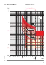
Страница 21: ...19 Curva a tempo normalmente inverso Fig 9b Normally inverse time curve...
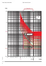
Страница 22: ...20 Fig 9c Curva a tempo molto inverso Very inverse time curve...
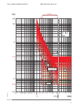
Страница 23: ...21 Fig 9d Curva a tempo estremamente inverso Extremely inverse time curve...
Страница 43: ......


