32
16.4.3. Esempio di impostazione
Si riporta ora un esempio di impostazione della protezione
omopolare di 2
a
soglia (50N).
Si vuole realizzare una protezione con le seguenti caratteri-
stiche:
– l'interruttore in oggetto monta TA da 80 A ed è privo di toroide
esterno
– Io>
= 40 A
– Io>>
= 300 A
– to>>
= 0,2 s.
a) Si seleziona tramite i dip-switch relativi il tipo di TA montato
sull'interruttore (fig. 11 - rif. 27).
b) Si seleziona il valore Io> = 40 A predispondendo i dip-
switch relativi in modo da ottenere la somma 0,5 (fig. 11 -
rif. 8).
c) Si calcola il rapporto Io>> / Io>, cioè, 300 A / 40 A = 7,5.
Si selezionano i dip-switch relativi alla funzione Io<< in
modo tale che la somma sia 7,5 (fig. 11 - rif. 11).
d) Si seleziona il tempo desiderato to>> = 0,2 s agendo sui dip-
switch relativi (fig. 11 - rif. 12).
e) Si seleziona tramite il dip-switch (fig. 11 - rif. 13) il tipo di
toroide omopolare (interno in questo caso) (vedi cap. 15).
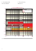
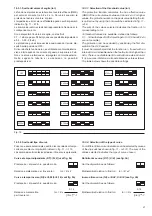
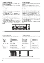
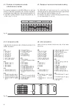
La configurazione riportata in figura 17 realizza l'impostazione
richiesta.
Fig. 17
17. Connessioni unità
Legenda delle connessioni unità in riferimento alla fig. 18 con
relative descrizioni:
XK1
XK3
1 Inizio fase L1
1 Solenoide d'apertura (+)
2 Fine fase L1
2 Solenoide d'apertura (-)
3 Inizio fase L2
4 Fine fase L2
XK5
5 Inizio fase L3
1 Non utilizzato
6 Fine fase L3
2 Comando di apertura a distanza (a)
7 Inizio toroide esterno
3 Non utilizzato
8 Fine toroide esterno
4 Non utilizzato
5 Non utilizzato
XK2
6 Contatto bistabile SRE (a)
1 Ingresso Vaux (+)
7 Contatto bistabile SRE (b)
2 Ingresso Vaux (-)
8 Contatto bistabile µP (a)
3 Non utilizzato
9 Contatto bistabile µP (b)
4 Non utilizzato
10 Comando di apertura a distanza (b)
Fig. 18
Io>>
Io>
OFF
0
0
0
0
0,05
0
0
0
0
2,5
1
2
5
9,5
0,8
0,4
0,2
0,1
0,05
INT
1
2
3
4
5
6
7
8
XK1
1
2
1
2
3
4
XK3
XK2
1
2
3
4
6
7
8
9
10
XK5
to>>
Tor.
EXT
16.4.3. Example of setting
An example of setting the second homopolar threshold (50N)
is now given.
A protection with the following characteristics is required:
– the circuit-breaker in question has a 80 A CT mounted and
does not have an external toroidal transformer
– Io> = 40 A
– Io>> = 300 A
– to>> = 0.2 s.
a) The type of CT mounted on the circuit-breaker is selected
by means of the relative dip-switches (fig. 11 - ref. 27)
b) The value of Io> = 40 A is selected by setting the relative dip-
switches so that a sum of 0.5 is obtained (fig. 11 - ref. 8)
c) The Io>> / Io> relation is calculated, i.e. 300 A / 40 A = 7.5.
The dip-switches relative to the Io<< function are selected
so that the sum is 7.5 (fig. 11 - ref. 11).
d) The desired time to>> = 0.2 s is selected by using the relative
dip-switches (fig. 11 - ref. 12).
e) The type of homopolar toroidal transformer used (in this
case, internal) is selected by means of the dip-switch (fig.
11 - ref. 13) (see chap. 15).
The configuration shown in figure 17 carries out the required
setting.
XK1
XK3
1 Start of L1 phase
1 Opening solenoid (+)
2 End of L1 phase
2 Opening solenoid (-)
3 Start of L2 phase
4 End of L2 phase
XK5
5 Start of L3 phase
1 Not used
6 End of L3 phase
2 Remote opening control (a)
7 Start of external toroid
3 Not used
8 End of external toroid
4 Not used
5 Not used
XK2
6 Bistable contact SRE (a)
1 Input Vaux (+)
7 Bistable contact SRE (b)
2 Input Vaux (-)
8 Bistable contact µP(a)
3 Not used
9 Bistable contact µP(b)
4 Not used
10 Remote opening control (b)
17. Unit connections
Caption to the unit connections with reference to fig. 18 with
relative descriptions:
Содержание PR512
Страница 2: ......
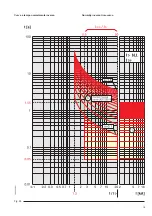
Страница 21: ...19 Curva a tempo normalmente inverso Fig 9b Normally inverse time curve...
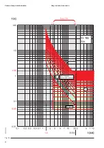
Страница 22: ...20 Fig 9c Curva a tempo molto inverso Very inverse time curve...
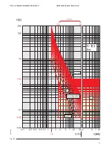
Страница 23: ...21 Fig 9d Curva a tempo estremamente inverso Extremely inverse time curve...
Страница 43: ......

