


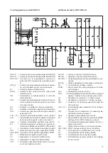


23
118
160
2
3
1
4
5
1
10
100
M4
XK4
XK5
XK6
XK2
XK1
XK3
30
30
130
130
120
27,5
KF301
64
32,3
M4
33,7
89
23
18
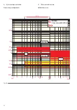
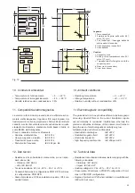
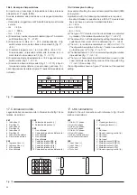
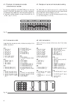
Fig. 10
Legenda
1 Area connettori
2 Foratura della porta della cella (161
mm x 131 mm)
3 Fori filettati per il fissaggio dell'unità
alla squadra di supporto
4 Vista posteriore (connettori)
5 Vista dall'alto.
Caption
1 Connector area
2 Drilling of the compartment door (161
mm x 131 mm)
3 Threaded holes for fixing the unit to the
support square
4 Rear view (connectors)
5 View from above.
10. Ambient conditions
• Operating temperature
– 5 ... + 40 °C
• Storage temperature
– 40 ... + 90 °C
• Relative humidity without condensation 90%
11. Electromagnetic compatibility
The galvanized iron box provides efficient electromagnetic
screening. Special filters on the current transformer inputs
ensure immunity to conducted interferences, whereas the
precise construction technique of the printed circuit helps to
keep the level of electromagnetic sensitivity very low.
Suitability tests and reference Standards
• Electrostatic discharges
IEC 801.2
• Radiated magnetic field
IEC 801.3
• Short-time transients
IEC 801.4
• High frequency interference
IEC 255 para. E5
12. Technical data
• Resistance to mechanical stresses, tests complying with the
following standards:
– Vibrations: IEC 68-2-6
– Impact: IEC 68-2-27
• Auxiliary voltage: 24 V dc -20% ... 30 V dc +10%
• Consumption: 50 mA max in PR512/P configuration; 15 mA
max in PR512/PD configuration
• Degree of protection: IP30 when installed in a switchboard;
IP42 with front cover.
10. Condizioni ambientali
• Temperatura di funzionamento
– 5 ... + 40 °C
• Temperatura di immagazzinamento
– 40 ... + 90 °C
• Umidità relativa senza condensazione
90%
11. Compatibilità elettromagnetica
La scatola in ferro zincato provvede ad una efficiente scher-
matura elettromagnetica. Opportuni filtri sugli ingressi dei
trasformatori di corrente garantiscono l'immunità dai disturbi
condotti, mentre l'accurata tecnica di costruzione del circuito
stampato contribuisce a mantenere molto basso il livello di
suscettibilità elettromagnetica.
Prove di idoneità e Norme di riferimento
• Scariche elettrostatiche
IEC 801.2
• Campo magnetico irradiato
IEC 801.3
• Transitori di breve durata
IEC 801.4
• Disturbi alta frequenza
IEC 255 par. E5
12. Dati tecnici
• Resistenza alle sollecitazioni meccaniche, prove rispon-
denti alle norme:
– Vibrazioni IEC 68-2-6
– Urto IEC 68-2-27
• Tensione ausiliaria: 24 V cc -20% ... 30 V cc +10%
• Consumi 50 mA max in configurazione PR512/P; 15 mA max
in configurazione PR512/PD
• Grado di protezione: IP30 se installato in quadro; IP42 con
calotta frontale.
Содержание PR512
Страница 2: ......
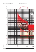
Страница 21: ...19 Curva a tempo normalmente inverso Fig 9b Normally inverse time curve...
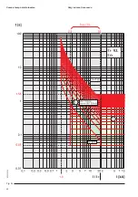
Страница 22: ...20 Fig 9c Curva a tempo molto inverso Very inverse time curve...
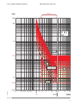
Страница 23: ...21 Fig 9d Curva a tempo estremamente inverso Extremely inverse time curve...
Страница 43: ......


