background image

I.L. 40-386.12

2-8

2

When a reclosing sequence is initiated for any of the above conditions, the recloser goes
through different stages; Recloser dead time countdown, waiting for synchronism/HBDL/HLDB
(if selected with the sync-check option), closing of contacts and reset. If in the reset phase the
condition to initiate the next reclosure appears, the recloser proceeds to the next reclosure. Oth-
erwise, at the end of the reset time, the recloser returns to READY state, which marks the end
of the sequence.

The sequence can also end in the LOCKOUT state for any of the reasons explained in Section
2.5.6 (Lockout Mode).

During the reclosing sequence, the different stages are displayed with the corresponding count-
downs and set timers.

2. 7

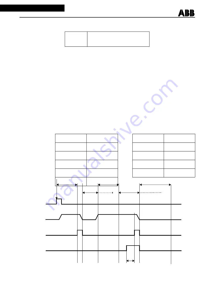
TIMING DIAGRAM FOR A TYPICAL RECLOSING SYNC-CHECK SEQUENCE

Timing Diagram showing a typical Reclosing/Sync-check sequence according to the following
enabled settings and conditions.

NOTE:

In the example below, 2 reclosures were selected: Reclosure 1 (Recl 1) was initiated by
3RI only. Reclosure 2 (Recl 2) was initiated by 52b only with HLDB condition enabled and
a Recl 2 Wait Time set indefinitely, i.e., “No Time Limit”.

52b or 3RI

Either signals will initiate a new reclo-
sure.
Internal 3RI or External RI

Relevant Settings for this example:

Sync Set ?

Yes

Recl 2

52b Only

Sync Time

2.0 Sec

Recl2 HLDB

Yes

Recl 1

3RI Only

Recl2 HBDL

No

Recl1 HLDB

No

Recl2 Sync

No

Recl1 HBDL

No

Recl2 Wait

No Time Limit

Recl1 Sync

No

Table 2-5:

3RI

52b

Close

HLDB

Sync Time

Recl 1

Reset

Recl 2

Wait Time

Reset

Ready

Ready

Trip

Relay

Содержание MV3B1RN5CB

Страница 1: ......

Страница 2: ...enance and all details and variations of this equipment do not pur port to be covered by these instructions If further information is desired by purchaser regarding a particular in stallation operation or maintenance of equipment the local ABB representative should be contacted Copyright ASEA BROWN BOVERI ABB Power T D Company Inc 1993 1994 1995 1996 1997 This document contains information that is...

Страница 3: ... on the appropriate schematic diagram and associated parts information Equipment Repair Repair work is done most satisfactorily at the factory When returning equipment contact your field sales rep resentative for RMR authorization All equipment should be returned in the original packing containers if possi ble Any damage due to improperly packed items will be charged to the customer Document Overv...

Страница 4: ...NG AND SYNCH CHECK OPTION 2 1 2 2 TEST PLUGS AND FT SWITCHES 2 1 2 3 EXTERNAL WIRING 2 1 2 4 RECLOSING SYNC CHECK DESCRIPTION 2 2 2 4 1 DISPLAY MODULE MMI 2 2 2 4 2 LED INDICATORS 2 2 2 4 3 LEDS AND DISPLAY RESET 2 2 2 5 FRONT PANEL OPERATION 2 4 2 5 1 READY MODE 2 4 2 5 2 SETTINGS MODE SET 2 4 2 5 3 TARGETS MODE 2 5 2 5 4 STATISTICS MODE 2 5 2 5 5 TEST MODE 2 6 2 5 6 LOCKOUT MODE 2 7 2 5 7 DISABL...

Страница 5: ...EAR VIEW OF REL 301 302 WITH RECLOSER SYNCH CHECK OPTION INSTALLED 2 3 FIGURE 2 2 REL 301 302 SYSTEMS EXTERNAL CONNECTION SHEET 1 2 26 FIGURE 2 3 REL 301 302 SYSTEMS EXTERNAL CONNECTION SHEET 2 2 27 FIGURE 2 4 CONNECTION DIAGRAM FOR A PHASE TO GROUND SYNC POTENTIAL 2 28 FIGURE 2 5 CONNECTION DIAGRAM FOR PHASE TO PHASE SYNC POTENTIAL 2 29 ...

Страница 6: ...e voltage synchro nism check settings will be displayed only when the manual close function is enabled Man Close Yes and the optional voltage synchronism check logic is present a Man Close Yes No Enable disable manual close function b Man HLDB Yes No Manual close with Hot Line Dead Bus voltage check b Man HBDL Yes No Manual close with Hot Bus Dead Line voltage check c Man SYNC Yes No Manual close ...

Страница 7: ...Disabled when reclosure is disabled by setting choice 5 Improved recloser flexibility by changing action taken by logic when maximum number of reclosures set ting Cum Recl is reached Now instead of the recloser locking out the alarm AL1 is set 6 Improved function of RECLOSING IN SERVICE LED to reflect loss of dc reclosing module failure reclos ing being disabled by setting choice and or Man Machin...

Страница 8: ......

Страница 9: ...initiating close either directly or through optional Voltage Synchronism check logic Two electrically separate close contacts CLOSE 1 2 for breaker closing Contact closure duration 0 01 2 seconds Failed Reclose function Failed Reclose time 1 250 seconds Max cycle function Max cycle time 1 990 seconds Follow breaker function Breaker operation and maintenance control Programmable maximum reclosures ...

Страница 10: ...tion d Reclosing event recording e Test functions 1 5 SELF CHECKING SOFTWARE Self checking software includes the following functions a Program Memory Check Sum Immediately upon power up the relay does a complete EPROM checksum of program memory Afterwards the Reclosing Relay continually verifies the program memory check sum b Power Up RAM Check Immediately upon power up the relay does a complete t...

Страница 11: ...Bus Dead Line HBDL or Hot Line Dead Bus HLDB logic For relays supplied with internal synchronism checking logic supervision of REL 301 302 re closing is settable for synchronism and or HBDL and or HLDB for each reclosing attempt REL 301 302 reclosing option syn chronism checking logic utilizes a windshield wiper characteristic see Figure 1 2 This is a combination of synchronism voltage magnitude m...

Страница 12: ...ge option i e REL 301 302 style number digit 6 is a T corrects for the 30o phase shift difference between line to neutral protection voltage in put and line to line synchronism voltage input Components have been added to hardwire the phase shift compensation Hence when viewing the Bus Line Angle on the Man Machine Interface MMI display synchronism is represented by 0o angular difference between Bu...

Страница 13: ...osing w sync check 120V T None N PILOT SYSTEM Pilot REL302 P Non Pilot REL301 N PROGRAMMABLE CONTACT OUTPUTS 5 Contacts including one trip rated contact 5 None N COMMUNICATIONS PORT Flexible PONI Rear mounted NET C RS 232C Default R RS 232C with IRIG B Input B FRONT PANEL INTERFACE LCD Display L RS 232C PONI R Both B None N FT Test plug style 13B8453G05 1 8 REL 301 302 Catalog Numbers For Referenc...

Страница 14: ...TS OF ANY FT 10 SWITCH THEY MAY BE ENERGIZED c Release frame latches by pushing the top and bottom left and right ends for horizontal mount relay latches inward towards the center of the relay d Push the center latch on the side of the relay towards the middle of the frame to release the inner chassis e Slide out the inner chassis f Mount the Recloser Synch check Module in the middle connector on ...

Страница 15: ...e switch must be on Recloser TABLE 2 1 CONNECTION SPECIFICATION CHART FOR RECLOSER SYNC CHECK OPTION INPUT OUTPUTS LOCATION SIGNAL INPUTS Reclosing Synch check Connection Add Following Connections HOLD 2 Terminals on Terminal Strip TB5 EXT RI 2 Terminals on Terminal Strip TB5 DR LOCK 2 Terminals on Terminal Strip TB4 LINE VOLTAGE Vs Vsr FT 9 and FT 10 BUS VOLTAGE Va Vb or Vc Voltage reference sele...

Страница 16: ......

Страница 17: ...02 mode display selection scrolling within a selected mode and ac cepting relay settings The display default mode is automatically returned to when no push button has been depressed for 2 minutes The display default mode is defined in Table 2 3 By keeping the SELECT push button depressed the list of modes is scrolled in the sequence shown in Table 2 3 at approximately a one second rate For each se...

Страница 18: ...o move to the next setting since some settings might not be displayed as the result of another setting choice For example selecting 2 reclosures disables the display of settings for reclosures 3 and 4 Likewise when a function works in conjunction with a timer disabling the function hides the timer setting 2 5 3 Targets Mode TR Change the mode to TR using the SELECT push button The relay saves the ...

Страница 19: ... appears on the display 2 5 5 Test Mode TEST Change the mode to TEST using the SELECT push button The test display provides diagnos tic LED and output contact testing capabilities for the REL 301 302 recloser module Output Contacts and LED tests Scroll through the functions in the TEST mode using the RAISE or LOWER push buttons until the output contact to be tested appears in the function field of...

Страница 20: ... Disabled state and the display shows the text Recloser Disabled Check Setting the Recloser In service LED will also go out Settings Targets Statistics and Test modes can still be accessed when the recloser is disabled To re enable the recloser set the Recloser back to Enabled The recloser returns then to Ready mode after resetting from LOCKOUT The Recloser In Service LED will light when the reclo...

Страница 21: ...displayed with the corresponding count downs and set timers 2 7 TIMING DIAGRAM FOR A TYPICAL RECLOSING SYNC CHECK SEQUENCE Timing Diagram showing a typical Reclosing Sync check sequence according to the following enabled settings and conditions NOTE In the example below 2 reclosures were selected Reclosure 1 Recl 1 was initiated by 3RI only Reclosure 2 Recl 2 was initiated by 52b only with HLDB co...

Страница 22: ...ECI 1 Recl n Init 52b only 3RI only 52b and 3RI 52b or 3RI 52b Only Reclose Block Recl1 must be set to one of the setting choices that includes 3RI to view this setting Recl1 RB Recl n RB No Yes No Reclose 1 Dead Time Recl1 Time Recl n Time 0 01 0 99 Step 0 01 sec 1 0 9 9 Step 0 1 sec 10 250 Step 1 sec 0 50 sec Reclose 1 on HLDB Recl1 HLDB Recl n HLDB No Yes No Reclose 1 on HBDL Recl1 HBDL Recl n ...

Страница 23: ...9 9 Step 0 1 sec 10 250 Step 1 sec 10 sec Reclose 3 on HLDB Recl3 HLDB Recl n HLDB No Yes No Reclose 3 on HBDL Recl3 HBDL Recl n HBDL No Yes No Reclose 3 on Synchronism Recl3 Sync Recl n Sync No Yes No 3 Max Wait Time for a HLDB HBDL or Synchronism condition Recl3 HLDB HBDL or Sync must be yes to view this set ting Recl3 Wait Recl n Wait 0 99 Step 1 sec 100 990 Step 10 sec No time Limit Infinite T...

Страница 24: ...le MaxCycle No Yes No Maximum Cycle Time Max Cycle must be Yes to view this setting Max Time Max Time 1 99 Step 1 sec 100 990 Step 10 sec 990 sec Enable FollowBr Follow Bkr No Yes No Use of 52aInput 52a Mancls 52a ManCls 52a Yes Manual Close No Dis abled No Disabled Number of Reclosures to Alarm Enable Cum Recl Cum Recl No Yes No Number of Reclosures to Alarm Cum Recl must Yes to view this setting...

Страница 25: ...al Close if Synchronism Manual Max Wait Time for a HLDB HBDL or Synchronism Condition Man HLDB HBDL or Sync must be yes to view this setting Man Close Man HLDB Man HBDL Man SYNC Man Wait Man Close Man HLDB Man HBDL Man SYNC Man Wait No Yes No Yes No Yes No Yes 0 99 in 1 Second steps 100 990 in 10 Second steps Infinite Time No Time Limit No No No No 60 sec Recloser Enable Disable Recloser Recl Enab...

Страница 26: ...ppears The status should show the value 0 Using the RAISE push button move to the function Close Relay Contacts Pressing the EN TER push button should energize both close relays CLOSE 1 and CLOSE 2 as long as ENTER is depressed Proceed to a similar test for the Lockout Contact and LED the In progress Contact the Fail Contact and LED and the all LEDs for the Recloser These functions follow the Clos...

Страница 27: ...I L 40 386 12 2 14 2 Figure 2 2 Reclosing Option Module Component Layout Sub 4 1614C19 LOCKOUT FAILRECLOSE IN PROGRESS DRIVE TO LOCKOUT HOLD External RI OUT 2 OUT 1 ...

Страница 28: ...e close relay contacts close the breaker and the reset process is entered Check that the reclosure returns to READY after resetting and that the IN_PROGRESS contact is de energized c 4 Apply the fault as in b 4 above but this time during the reset re apply the fault The relay should perform the second reclosure followed by a reset In that reset phase apply the fault again and the relay should go t...

Страница 29: ...e Check that the reclosure returns to READY and that the IN_PROGRESS contact is opened a 3 Check of 52b Initiation for Reclose 2 Change the setting of Recl 2 to 52b or 3RI Trip the breaker simulator apply rated dc voltage to the 52b input and during the reset process re trip the breaker The IN_PROGRESS output contact will close and remain closed The relay will skip the remaining reset time and beg...

Страница 30: ...close 1 dead time timing begins Apply rated dc voltage to the HOLD input during the reclos ing dead time the countdown stops Remove the voltage from the HOLD input and note the count down continues When it expires the close relay contact closes the breaker the reset timer counts down and the relay returns to READY a 8 Check of 52a Input and 52a Mancls Logic Change the 52a Mancls setting to Yes 52a...

Страница 31: ...s set to Line and verify that jumper P12 on the Filter Module see I L 40 386 1 Figure 5 1 is in the top position In this example Va is cho sen to be the reference Bus voltage Connect a voltage source to Va and Vn Bus voltage inputs FT 1 polarity and FT 4 non polarity Connect another voltage source to the VS and VSR Line voltage inputs FT 10 polarity and FT 9 non polarity Apply both voltages not to...

Страница 32: ...ould be lit as verification Note that a Sync Time timer count down occurs in addition to the Reset timer count down a 3 Check of Reclose Sequence with Synchronism Check Condition Apply a volt age above VMax to both the Bus and Line voltage inputs The angle between the two voltages must be less than the Sync Angle setting Repeat the test in Para graph 2 8 Section c 2 Reclosure 1 should be successfu...

Страница 33: ...ed the reclosing sequence will complete successfully after the reset time Change the Recl1 Sync and the Recl2 Sync settings to Yes and return to READY by pressing the RESET push button a 6 Check of Reclose Sequence without Synchronism Condition Repeat the test in Section 2 11 Paragraph a 5 above Apply a voltage above the setting value of V Max to both the Bus voltage and Line voltage inputs with a...

Страница 34: ...and 52b or 3RI allow either 52b and 3RI or 52b to initiate the n reclosure Recln RB If one of the setting choices for reclose initiation Recl n includes 3RI and Recln RB is set to yes a Reclose Block signal from the protection will prevent the n relosing event from initiating For example Recl n is set to 3RI Only An external device energizes the External RI input and the protection logic issues a ...

Страница 35: ... it is possible for the Max Time to expired and cause an undesired LOCKOUT Follow Breaker This function is to prevent sustained pumping action of a circuit breaker as a result of a permanent fault or any mechanical malfunction which causes the breaker to be closed by some means other than the designed reclosing relay action This function allows the relay to follow the 52b contact action While the ...

Страница 36: ...en for a set period of time which is the Re covery time The three parameters Max Count Duration and Recov ery are detailed by the circuit breaker manufacturer Output n Output contacts 1 and 2 can be configured for seven function of indica tions The functions choices are listed in Table 2 6 Remote Set When selected setting changes are allowed via the communications port s This setting must be set t...

Страница 37: ...us are considered in syn chronism Recln HLDB When set to Yes permits a reclosure when the Line is live and the Bus is dead n represents the reclosure number 1 4 Recln HBDL When set to Yes permits a reclosure when the bus is live and the line is dead n represents the reclosure number 1 4 Recln Sync When set to Yes permits a reclosure when the synchronism condition is fulfilled n represents the recl...

Страница 38: ...tch contact should be wired to this input to insure the recloser goes to and remains in the LOCKOUT mode while the breaker is open External Reclose Initiate This is the optically isolated input EXT RI and is used to initiate the recloser externally This input is useful when the recloser is shared by other protection devices e g primary and backup relay ing Initiation from this input is enabled by ...

Страница 39: ...I L 40 386 12 2 26 2 Figure 2 2 REL 301 302 Systems External Connection Sub 1 1618C74 Sheet 1 of 2 ...

Страница 40: ...I L 40 386 12 2 27 2 Figure 2 3 REL 301 302 Systems External Connection Sub 1 1618C74 Sheet 2 of 2 ...

Страница 41: ... 40 386 12 2 28 2 FT 15 FT 17 FT 19 52 A B C FT 10 FT 9 FT 1 FT 2 FT 3 FT 4 REL 301 302 Figure 2 4 Connection Diagram for A Phase To Ground Sync Potential TRIP DIRECTION Note Jumper P12 set to Va Position ...

Страница 42: ... 2 29 2 FT 15 FT 17 FT 19 52 A B C FT 10 FT 9 FT 1 FT 2 FT 3 FT 4 REL 301 302 Figure 2 5 Connection Diagram for Phase To Phase Sync Potential TRIP DIRECTION Note Jumper P12 set to Va Position with ABC phase rotation ...

Отзывы: