ABB MicroFlex e150 Скачать руководство пользователя страница 65

Electrical installation: input / output   65

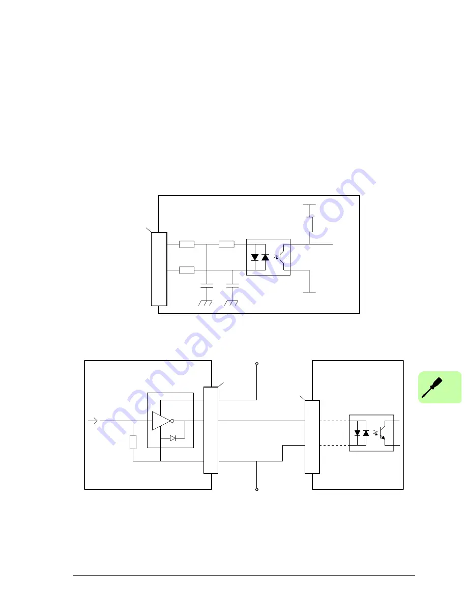
Digital inputs - general purpose DIN0, DIN3

Location: X3, pins 17 & 7 (DIN0), 15 & 5 (DIN3)

These general purpose digital inputs are buffered by a TLP280 opto-isolator, allowing 
the input signals to be connected with either polarity. The inputs do not share a 
common reference. When the MicroFlex e150 is connected to Mint WorkBench, the 
digital inputs can be configured using the Digital I/O tool. Alternatively, Mint keywords 
including 

DRIVEENABLEINPUT

RESETINPUT

ERRORINPUT

 and 

STOPINPUT

 can be 

used. The state of the digital inputs can be viewed using the Mint WorkBench Spy 
window's Axis tab. See the Mint help file for details. 

General purpose digital input - DIN0 shown:

Digital input - typical connections from an ABB NextMove e100:

33R

33R

3k3

Vcc

DGND

17

7

DIN0-

DIN0+

MicroFlex 

e

150

X3

TLP280

Mint

UDN2982

Mint
DRIVEENABLEOUTPUT

MicroFlex 

e

150

USR GND

DOUT0

DIN0-

17

10k

TLP280

7

10

1

9

DIN0+

USR V+

X11

X3

NextMove e100 / controller

User
supply
24 V

User
supply
GND

Содержание MicroFlex e150

Страница 1: ...ABB motion control User s manual MicroFlex e150 servo drive MN1961WEN ...

Страница 2: ...he inside of the back cover For manuals not available in the Document library contact your local ABB representative Drive hardware manuals and guides Code English MicroFlex e150 Quick Installation Guide LT0307 Safety Manual Safe Torque Off STO function for MicroFlex e150 drives LT0313 MicroFlex e150 wall chart LT0296 MicroFlex e150 flyer 3AUA0000097609 ...

Страница 3: ...r s manual MicroFlex e150 LT0291A04EN EFFECTIVE 2013 12 01 2013 ABB Oy All Rights Reserved 1 Safety Table of contents 4 Mechanical installation 6 Electrical installation AC input motor and brake 9 Start up ...

Страница 4: ......

Страница 5: ...breviations 18 General terms 18 Trademarks 19 3 Hardware description What this chapter contains 21 Features 21 Operating principle 22 Product overview 23 Connections front panel 23 Connections top panel 24 Type designation label 25 4 Mechanical installation What this chapter contains 27 Requirements for the installation site 27 Required tools 28 Checking the delivery 28 Mounting and cooling 29 Eff...

Страница 6: ... Power supply filters 48 Harmonic suppression 48 Reversing the filter 48 Power disconnect and protection devices 49 Drive overload protection 50 24 V control circuit supply 51 Motor connections 52 Motor power cable shielding 53 Motor circuit contactors 55 Sinusoidal filter 55 Motor brake connection 55 Thermal switch connection 57 Brake resistor regeneration resistor 58 7 Electrical installation in...

Страница 7: ...ains 89 Introduction 89 Connecting the MicroFlex e150 to the PC 90 Installing Mint WorkBench 90 Starting the MicroFlex e150 91 Preliminary checks 91 Power on checks 91 USB driver 91 Configuring the TCP IP connection optional 93 Configuring the PC network adapter 93 Mint Machine Center 94 Starting MMC 95 Mint WorkBench 96 Help file 97 Starting Mint WorkBench 98 Commissioning Wizard 100 Further tuni...

Страница 8: ...n DC bus ripple voltage 131 Temperature derating 132 Derating characteristic for 3 A models E152A03 132 Derating characteristic for 6 A models E152A06 133 Derating characteristic for 9 A models E152A09 134 Overtemperature trips 134 Heat dissipation 135 Recommended fuses circuit breakers and wire sizes 136 Input power cycling and inrush 137 Discharge period 137 Power supply filters 138 24 V control...

Страница 9: ...nce with the European EMC Directive 153 Compliance with the EN 61800 3 154 Definitions 154 Category C2 154 Category C3 154 Compliance with the European Machinery Directive 155 Validating the operation of the Safe Torque Off function 155 CE Declaration of Conformity 156 UL marking 157 UL checklist 157 Control system 158 Servo configuration 158 Torque servo configuration 160 12 Accessories What this...

Страница 10: ...on 176 Technical data Digital inputs STO1 STO2 X3 177 STO function data related to safety standards 177 STO function TüV certificate 178 Further information Product and service inquiries 179 Product training 179 Providing feedback on ABB Drives manuals 179 Document library on the Internet 179 ...

Страница 11: ...pacitors discharge before you start working on the drive motor or motor cable Always ensure by measuring with a multimeter impedance at least 1 Mohm that there is no voltage between the drive input phases L1 L2 and L3 and the ground Do not work on the control cables when power is applied to the drive or to the external control circuits Externally supplied control circuits can carry dangerous volta...

Страница 12: ...lace where the machine is to be used In Europe these are the Machinery Directive the ElectroMagnetic Compatibility Directive and the Low Voltage Directive In the United States this is the National Electrical code and local codes To comply with CE directive 2004 108 EC an appropriate AC filter must be installed Motor overtemperature sensing is required to satisfy UL 508C The drive has no provisions...

Страница 13: ...eplacement When operating a rotary motor with no load coupled to its shaft remove the shaft key to prevent it flying out when the shaft rotates Operating the MicroFlex e150 in torque mode with no load attached to the motor can cause the motor to accelerate rapidly to excessive speed Make sure that dust from drilling does not enter the drive during the installation Electrically conductive dust insi...

Страница 14: ...tion after a fault Do not control the motor with an AC contactor or disconnecting device disconnecting means use instead external commands I O or fieldbus If a drive enable signal is already present when power is applied to the MicroFlex e150 the motor could begin to move immediately The metal heat sink on the left side of the MicroFlex e150 can become very hot during normal operation MEDICAL DEVI...

Страница 15: ...ry and installing and commissioning the drive The flowchart refers to chapters sections in this manual Applicability The manual is applicable to the MicroFlex e150 drive Target audience The reader is expected to know the fundamentals of electricity wiring electrical components and electrical schematic symbols The manual is written for readers worldwide Both SI and imperial units are shown Purpose ...

Страница 16: ...tions including the AC supply motor output and brake resistor Electrical installation input output page 59 describes the installation of low power connections including analog and digital input outputs including Safe Torque Off motor feedback and Ethernet Installation checklist page 87 provides a list of checks to confirm that the physical installation has been completed correctly Start up page 89...

Страница 17: ...npack and check the units only intact units may be started up Check that all necessary optional modules and equipment are present and correct Mount the drive Checking the delivery page 28 Mounting and cooling page 29 Route the cables Routing the cables page 39 Check the insulation of the supply cable the motor and the motor cable Checking the insulation of the assembly page 44 Connect the power ca...

Страница 18: ...og to Digital Converter ASCII American Standard Code for Information Interchange AWG American Wire Gauge CDROM Compact Disc Read Only Memory CiA CAN in Automation International Users and Manufacturers Group e V CTRL E on the PC keyboard press Ctrl and E at the same time DAC Digital to Analog Converter DS402 CiA Device Profile for Drives and Motion Control EDS Electronic Data Sheet EMC Electromagne...

Страница 19: ...ed technology licensed by Beckhoff Automation GmbH Germany Windows XP Windows Vista and Windows 7 are registered trademarks of the Microsoft Corporation NC Not Connected RF Radio Frequency SSI Synchronous Serial Interface TCP IP Transmission Control Protocol Internet Protocol UDP User Datagram Protocol Unit term abbreviation Description ...

Страница 20: ...20 Introduction to the manual ...

Страница 21: ...induction motors Range of models with continuous current ratings of 3 A 6 A or 9 A Direct connection to 115 V AC or 230 V AC single phase or 230 V AC three phase supplies Universal feedback interface supporting incremental encoder BiSS SSI EnDat SinCos or Smart Abs feedback Position velocity and current control 10 optically isolated general purpose digital inputs Two inputs have fast input capabil...

Страница 22: ...The capacitor bank of the intermediate circuit stabilizes the DC voltage The inverter converts the DC voltage back to AC voltage for the AC motor The brake chopper connects the external brake resistor to the intermediate DC circuit when the voltage in the circuit exceeds its maximum limit R1 R2 U V W L1 L2 L3 Rectifier Capacitor bank Inverter Brake chopper AC supply AC motor ...

Страница 23: ...in Incremental BiSS SSI Smart Abs EnDat 2 1 SinCos EnDat 2 2 1 CHA Data Data Data NC 2 CHB Clock NC Clock NC 3 CHZ NC NC NC NC 4 Sense Sense Sense Sense Sense 5 Hall U NC NC Sin Sin 6 Hall U NC NC Sin Sin 7 Hall V NC NC Cos Cos 8 Hall V NC NC Cos Cos 9 CHA Data Data Data NC 10 CHB Clock NC Clock NC 11 CHZ NC NC NC NC 12 5 V out 5 V out 5 V out 5 V out 5 V out 13 DGND DGND DGND DGND DGND 14 Hall W ...

Страница 24: ...al 14 Shield 7 DIN4 13 CREF1 6 DIN5 12 DIN8 5 DIN6 11 DIN9 4 DIN7 10 USRV 3 CREF0 9 DOUT5 2 DOUT3 8 DOUT6 1 DOUT4 OPT1 Input Output E1 E2 EtherCAT 1 TX 2 TX 3 RX 4 NC 5 NC 6 RX 7 NC 8 NC Both connectors have identical pinouts EtherCAT IN E2 E1 EtherCAT OUT E1 is also used for standard Ethernet if DIP switch 4 is in the ON position see page 79 ...

Страница 25: ...ile to the drive CAT S No OUTPUT Desc INPUT U0316010002 9A Cont 18A Pk 0 250V 3Ø 3kW MicroFlex e150 Drive 9A 105 250 AC 50 60 Hz 1 3 Ø Ø Made in the UK F M H 2 A 0 3 T R E N 2 3 E152A09ENOA U0316010002 MicroFlex e150 Drive 9A E152A09EIOA E152A09ENOA E 1 5 2 A 0 9 E I O A x x x E15 2A 09 E A O I xxx MicroFlex e150 115 230 V AC supply input Rated amps 03 3 A 06 6 A 09 9 A Feedback E Universal Encode...

Страница 26: ...26 Hardware description ...

Страница 27: ...he flange The protective earth ground the threaded hole on the top of the MicroFlex e150 must be bonded to a safety earth ground using either a 25 A conductor or a conductor of three times the peak current rating whichever is the greater Avoid locating the MicroFlex e150 immediately above or beside heat generating equipment or directly below water steam pipes Avoid locating the MicroFlex e150 in t...

Страница 28: ... screws or bolts for mounting the MicroFlex e150 Wire stripper For UL installations use UL listed closed loop connectors that are of appropriate size for the wire gauge being used Connectors are to be installed using only the crimp tool specified by the manufacturer of the connector Checking the delivery Check that there are no signs of damage Notify the shipper immediately if damaged components a...

Страница 29: ...45 C 113 F and the absolute maximum ambient temperature of 55 C 131 F Within the ambient temperature range The 3 A model is designed to operate without any additional cooling methods The 6 A and 9 A models require a forced air flow passing vertically from the bottom to the top of the MicroFlex e150 case to allow full rated current at 45 C 113 F Temperature derating characteristics are shown in Tem...

Страница 30: ...nother MicroFlex e150 or other obstruction there should be a minimum space of 90 mm 3 5 in to maintain effective cooling Remember that a MicroFlex e150 will be receiving air that has been already heated if it is mounted above another MicroFlex e150 or heat source Multiple MicroFlex e150 units mounted above each other should be aligned not offset to promote air flow across the heat sinks It is reco...

Страница 31: ...cations See Dimension drawing all models on page 128 for complete dimensions 2 Position the drive and check the hole positions are correct 3 Drill the holes mount the drive and tighten all four screws until the drive is secure 167 7 mm 6 6 in 63 5 mm 2 5 in ...

Страница 32: ...32 Mechanical installation ...

Страница 33: ... ABB are not followed the drive might experience problems that are not covered by the warranty The installation methods described in this chapter will improve the reliability of the system reduce troubleshooting time and optimize the EMC electromagnetic compatibility behavior of the control system Checking the compatibility of the motor and drive Check that the 3 phase AC motor and the drive are c...

Страница 34: ...ases causes switching devices to break the load circuit before the opening of the main contacts of the disconnector EN 60947 3 a circuit breaker suitable for isolation in accordance with EN 60947 2 Other regions The disconnecting device must conform to the applicable safety regulations Emergency stop devices For safety reasons install emergency stop devices at each operator control station and at ...

Страница 35: ...s given in Technical data on page 136 The fuses protect the input cable in short circuit situations restrict drive damage and prevent damage to adjoining equipment in case of a short circuit inside the drive Fuses Recommended fuses are listed in Recommended fuses circuit breakers and wire sizes on page 136 Alternative fuses must be compatible fast acting types Circuit breakers It is highly recomme...

Страница 36: ...or must be equal to that of the phase conductor same cross sectional area 600 V AC cable is accepted for up to 500 V AC Refer to Technical data on page 154 for the EMC requirements A symmetrical shielded motor cable must be used to meet the EMC requirements of the CE and C Tick marks see the following diagrams A four conductor system is allowed for input cabling but a shielded symmetrical cable is...

Страница 37: ...minimum requirement of the motor cable shield of the drive is shown below It consists of a concentric layer of copper wires The better and tighter the shield the lower the emission level and bearing currents Symmetrical shielded cable three phase conductors and a concentric or otherwise constructed PE conductor and a shield Check with local state country electrical codes for allowance Note A separ...

Страница 38: ...odes DC in order to minimize the EMC emission at switch off If not suppressed the disturbances might connect capacitively or inductively to other conductors in the control cable and form a risk of malfunction in other parts of the system Install the protective component as close to the inductive load as possible Do not install protective components at the I O terminal block 1 Relay outputs 2 Varis...

Страница 39: ... 24 V DC and 115 230 V AC signals in the same cable Relay cable The cable type with braided metallic screen for example ÖLFLEX by LAPPKABEL has been tested and approved by ABB Connection of a motor temperature sensor to the drive I O See Thermal switch connection on page 57 Routing the cables Route the motor cable away from other cable routes Motor cables of several drives may be run in parallel i...

Страница 40: ...n below Separate control cable ducts Route 24 V and 230 V cables in separate ducts unless the 24 V cable is insulated for 230 V or insulated with an insulation sleeving for 230 V Control cables min 300 mm Motor cable Power cable Drive 12 in min 500 mm 20 in 24 V 24 V 230 V 230 V ...

Страница 41: ...ft Longer wires must be shielded as shown Wire colors can vary according to region Connect AC power cable shield to metal panel using conductive shield earth ground clamps On painted panels remove paint to expose bare metal Drive earth wire must be at least 10 mm2 7 AWG Protective Earth PE DO NOT TOUCH Brake resistors can become extremely hot Locate away from vulnerable components and wiring CAUTI...

Страница 42: ...42 Planning the electrical installation ...

Страница 43: ... be carried out by a qualified electrician Follow the instructions in chapter Safety on page 11 Ignoring the safety instructions can cause injury or death Make sure that the drive is disconnected from the input power during installation If the drive is already connected to the input power wait for 5 minutes after disconnecting the input power See the requirements in Electrical power network specif...

Страница 44: ...r cable according to local regulations before connecting to the drive Motor and motor cable Check the insulation of the motor and motor cable as follows 1 Check that the motor cable is connected to the motor and disconnected from the drive output terminals U V and W 2 Measure the insulation resistance between each phase conductor and the Protective Earth conductor using a measuring voltage of 500 ...

Страница 45: ...ning torque is 0 5 0 6 N m 4 4 5 3 lb in The threaded hole in the top or bottom of the case may be used as an additional functional earth ground connection for signals on connector X3 The threaded holes may also be used to attach shield or strain relief clamps The holes are threaded for M4 bolts no longer than 11 mm 0 43 in Earthing grounding A permanent earth ground bonding point is provided on t...

Страница 46: ...ch requires an earth connection to the unit whenever hazardous voltages are applied The equipment provides protection against electric shock by Means of connection of protective earth to accessible live conductive parts Basic insulation Earth leakage Maximum earth leakage from the MicroFlex e150 is 3 4 mA per phase 230 V 50 Hz supply This value does not include the earth leakage from the AC power ...

Страница 47: ... power factor correction capacitors that are switched on line and off line the capacitors must not be switched while the drive is connected to the AC power line If the capacitors are switched on line while the drive is still connected to the AC power line additional protection is required A Transient Voltage Surge Suppressor TVSS of the proper rating must be installed between the AC line reactor o...

Страница 48: ...AC supply a 13 mH 4 A rms 10 A peak line reactor is required to ensure compliance with EN 61000 3 2 class A limits when the total equipment supply load is less than 1 kW Reversing the filter When using filters FI0015A00 or FI0015A02 they must be reversed to ensure that the MicroFlex e150 complies with the CE specifications for which it has been tested The AC power supply should be connected to the...

Страница 49: ...s are not supplied see Recommended fuses circuit breakers and wire sizes on page 136 For CE compliance see Technical data on page 153 NOTE Metal conduit or shielded cable should be used Connect conduits so the use of a line reactor or RC device does not interrupt EMI RFI shielding Using 2 phases of a 3 phase supply Power can be derived by connecting two phases of an appropriate three phase supply ...

Страница 50: ...on The MicroFlex e150 will immediately trip and disable if there is an overload condition The parameters for managing drive overloads are configured automatically by the Commissioning Wizard page 100 If they need to be changed use the Parameters tool in Mint WorkBench page 112 ...

Страница 51: ...the MicroFlex e150 If other devices are powered from the same 24 V supply a filter part FI0014A00 should be installed to isolate the MicroFlex e150 from the rest of the system Alternatively a ferrite sleeve can be attached to the supply cable near connector X2 24 V filter optional Use a twisted pair cable with ferrite sleeve attached close to connector X2 Ferrite sleeve STAR POINT Incoming safety ...

Страница 52: ...g motor overloads are configured automatically by the Commissioning Wizard page 100 If they need to be changed or you are using an alternative motor use the Parameters tool page 112 WARNING Hazardous voltages can exist on the motor output connections Do not touch the motor output connections before you first ensure there is no high voltage present WARNING The motor cables U V and W must be connect...

Страница 53: ...ctor must provide contact with a large proportion of the cable s circumference The following diagram shows two possible methods Exposing the cable shield 1 Make a single circular cut in the cable s outer sheath ensuring that the cable s braided shield is not damaged 2 Slide the section of outer sheath towards the end of the cable to expose an area of braided shield Carefully remove the excess shea...

Страница 54: ...rcular cut in the cable s outer sheath ensuring that the cable s braided shield is not damaged 2 Slide the section of outer sheath towards the end of the cable to expose an area of braided shield Carefully remove the excess sheath at the end of the cable from MicroFlex e150 On painted panels remove paint to expose bare metal Optional Motor Cable Management Bracket OPT CM 001 recommended from Micro...

Страница 55: ...ilter is used to provide a better quality waveform to the motor reducing motor noise temperature and mechanical stress It will reduce or eliminate harmful dV dt values voltage rise over time and voltage doubling effects which can damage motor insulation This effect occurs most noticeably when using very long motor cables for example 30 5 m 100 ft or more ABB servo motors intended to be used with d...

Страница 56: ...elay allows time for the relay contacts to engage and the brake to release See the MOTORBRAKEDELAY keyword WARNING The 24 V DC power supply used to power the brake must be a separate supply as shown in the diagram Do not use the supply that is powering the MicroFlex e150 digital outputs The brake wires often carry noise that could cause erratic drive operation or damage The brake contacts must nev...

Страница 57: ...o configure a digital input for this purpose A typical circuit using DIN0 as the input is shown in the following diagram WARNING The 24 V DC power supply connected to the thermal switch must be a separate supply as shown in the diagram The thermal switch wires often carry noise that could cause erratic drive operation or damage The thermal switch contacts must never be wired directly to a digital ...

Страница 58: ...ct the correct resistor for the application see the Brake X1 section starting on page 140 Suitable brake resistors are listed in Resistor choice on page 143 The brake resistor output is conditionally short circuit proof WARNING Electrical shock hazard DC bus voltages can be present at these terminals Use a suitable heat sink with fan if necessary to cool the brake resistor The brake resistor and h...

Страница 59: ...put AOUT Analog Output DIN Digital Input DOUT Digital Output STO Safe Torque Off WARNING The work described in this chapter may only be carried out by a qualified electrician Follow the instructions in chapter Safety on page 11 Ignoring the safety instructions can cause injury or death Make sure that the drive is disconnected from the input power during installation If the drive is already connect...

Страница 60: ...ation X4 pins 3 7 AIN0 2 6 AIN1 5 AGND The analog inputs pass through a differential buffer and second order low pass filter with a cut off frequency of approximately 1 2 kHz In Mint analog inputs can be read using the ADC keyword See the Mint help file for full details of ADC ADCMODE and other related ADC keywords Input circuit For differential inputs connect input lines to AIN and AIN Leave AGND...

Страница 61: ...drive loads of 4 kΩ or greater Shielded twisted pair cable should be used The shield connection should be made at one end only In Mint the analog output can be controlled using the DAC keyword See the Mint help file for full details of DAC and other related DAC keywords Output circuit 24VDC 3 X4 7 AIN0 ADC 0 5 0V Nȍ Nȍ potentiometer MicroFlex e150 AD5530BRUZ X4 1 5 AOUT0 AGND 15V 15V Demand 100 ...

Страница 62: ...age 64 STO2 X3 DIN0 Separate General purpose input page 65 DIN1 Separate General purpose fast inputs page 66 DIN2 Separate DIN3 Separate General purpose input page 65 OPT 1 top panel DIN4 CREF1 General purpose inputs page 68 DIN5 DIN6 CREF0 General purpose inputs page 68 DIN7 DIN8 DIN9 X3 Status out DOUT0 Separate Status output page 69 Can also be used as a general purpose output X3 DOUT1 Separate...

Страница 63: ...ut optional If homing is being handled locally by the MicroFlex e150 the axis home switch if present must be wired directly to the home input on the MicroFlex e150 otherwise it will not be able to complete its internal homing routines The home switch input is configured using the Digital I O tool in Mint WorkBench or by using the Mint HOMEINPUT keyword Other HOME keywords define the homing sequenc...

Страница 64: ... additional hardware drive enable input is used to control the MicroFlex e150 it must not be wired with the STO input circuit The state of the STO inputs can be viewed using the Mint WorkBench Spy window s Axis tab See the Mint help file for details See Appendix Safe Torque Off STO on page 173 Safe Torque Off digital input STO1 Safe Torque Off digital input STO2 33R 6k8 33R Vcc DGND TLP281 18 8 SR...

Страница 65: ...ed using the Digital I O tool Alternatively Mint keywords including DRIVEENABLEINPUT RESETINPUT ERRORINPUT and STOPINPUT can be used The state of the digital inputs can be viewed using the Mint WorkBench Spy window s Axis tab See the Mint help file for details General purpose digital input DIN0 shown Digital input typical connections from an ABB NextMove e100 33R 33R 3k3 Vcc DGND 17 7 DIN0 DIN0 Mi...

Страница 66: ...red using the Digital I O tool Alternatively Mint keywords including DRIVEENABLEINPUT RESETINPUT ERRORINPUT and STOPINPUT can be used The state of the digital inputs can be viewed using the Mint WorkBench Spy window s Axis tab See the Mint help file for details General purpose fast digital input DIN1 shown Digital input typical connections from an ABB NextMove e100 TLP115 33R 33R 3k3 Vcc DGND 16 6...

Страница 67: ...onfigured using the LATCHTRIGGERCHANNEL keyword to become a fast latch input This allows the position of the axis to be captured in real time and read using the Mint keyword LATCHVALUE The input can be configured using the LATCHTRIGGEREDGE keyword to be triggered either on a rising or falling edge Further control of position capture is provided by various other keywords beginning with LATCH See th...

Страница 68: ...cted to Mint WorkBench the digital inputs can be configured using the Digital I O tool Alternatively Mint keywords including DRIVEENABLEINPUT RESETINPUT ERRORINPUT and STOPINPUT can be used The state of the digital inputs can be viewed using the Mint WorkBench Spy window s Axis tab See the Mint help file for details General purpose digital input DIN4 shown Digital input typical connections from an...

Страница 69: ...circuit The status output becomes active in the event of an error or when the STO function is activated When the MicroFlex e150 is connected to Mint WorkBench the active level of the output can be configured using the Digital I O tool Alternatively the Mint keyword OUTPUTACTIVELEVEL can be used The output s state is displayed in the Spy window See the Mint help file for details General purpose out...

Страница 70: ...itably rated diode must be fitted across the relay coil observing the correct polarity This is to protect the output from the back EMF generated by the relay coil when it is de energized Digital output circuit DOUT1 shown When the MicroFlex e150 is connected to Mint WorkBench the active level of the outputs can be configured using the Digital I O tool Alternatively the Mint keyword OUTPUTACTIVELEV...

Страница 71: ...imately 200 mA The fuse can take up to 20 seconds to reset after the load has been removed If the output is used to directly drive a relay a suitably rated diode must be fitted across the relay coil observing the correct polarity This is to protect the output from the back EMF generated by the relay coil when it is de energized Digital output circuit DOUT3 shown MicroFlex e150 DOUT1 CREF1 8 TLP280...

Страница 72: ...g the Digital I O tool Alternatively the Mint keyword OUTPUTACTIVELEVEL can be used The state of the outputs is displayed in the Spy window See the Mint help file for details DOUT3 typical connections to an ABB NextMove e100 MicroFlex e150 DOUT3 CREF1 8 TLP280 9 2 10 DIN4 USRV OPT1 X9 TLP127 User supply 24 V User supply GND NextMove e100 controller ...

Страница 73: ...s The maximum recommended cable length is 5 m 16 4 ft RS485 interface Location X6 The RS485 interface is used to connect third party serial devices such as operator panels and PLCs The interface can operate in 2 wire or 4 wire RS485 mode which is selected using the Configuration tool in Mint WorkBench The default mode is 2 wire RS485 57600 Baud 8 data bits 1 stop bit with no parity MicroFlex e150 ...

Страница 74: ...ment use big endian word order and byte order for Modbus protocols If this is incompatible with other Modbus equipment the word and byte order for the MicroFlex e150 can be changed in Mint WorkBench See the Mint WorkBench help file for details MicroFlex e150 ABB Keypad KPD202 501 RXA 8 5 3 2 7 1 3 6 2 5 TXA GND GND TXB RXB RXB TXB RXA TXA Serial X6 ...

Страница 75: ...icroFlex e150 to support standard Ethernet communication with a host PC running Mint WorkBench The connection uses a high level Immediate Command Mode ICM protocol to allow Mint commands Mint programs and even firmware to be sent to the controller over the Ethernet network The host PC must be connected to the controller either directly or via a switch as shown in the following diagram Connecting t...

Страница 76: ...ontrol MicroFlex e150 incorporates a built in multi port EtherCAT slave controller providing two ports for connection to other equipment This allows nodes to be connected in many configurations such as a ring star or tree with EtherCAT s self terminating technology automatically detecting breaks or an intended end of line If only one port is used for EtherCAT operation it must be the E2 IN port St...

Страница 77: ... xml file describes the drive s capabilities to the EtherCAT manager The ESI file can be uploaded from the MicroFlex e150 using the Configuration tool in Mint WorkBench 1 2 3 4 5 6 7 8 9 10 11 12 13 14 15 16 17 18 19 20 OUT IN OUT IN OUT IN OUT IN OUT IN OUT IN OUT IN OUT IN OUT IN OUT IN OUT IN OUT IN OUT IN OUT IN OUT IN OUT IN OUT IN OUT IN OUT IN OUT IN EtherCAT master Machine 1 MicroFlex e150...

Страница 78: ...ight cables have the TX pins of the connector at one end of the cable wired to the TX pins of the RJ45 connector at the other end of the cable Crossover cables have the TX pins of the connector at one end of the cable wired to the RX pins of the RJ45 connector at the other end of the cable Recommended cables are listed in Ethernet cables on page 172 Crossover or straight cables can be used Many Et...

Страница 79: ...no effect DIP switch settings Switch Description OFF ON 4 E1 OUT port EtherCAT mode E1 OUT port Standard Ethernet mode 3 Normal operation Firmware recovery mode 2 X6 port 2 wire TX RX or 4 wire TX disconnect 120 Ω termination resistor X6 port 2 wire TX RX or 4 wire TX connect 120 Ω termination resistor 1 X6 port 4 wire RX disconnect 120 Ω termination resistor X6 port 4 wire RX connect 120 Ω termin...

Страница 80: ...es only To prevent contact with other conductors or earths grounds unearthed ungrounded ends of shields must often be insulated Linear motors use two separate cables encoder and Hall The cores of these two cables will need to be wired to the appropriate pins of the 15 pin D type mating connector Connection summary Pin Increment encoder BiSS SSI or EnDat 2 2 Smart Abs Extra incremental encoder EnDa...

Страница 81: ...e on pin 12 to maintain a 5 V supply at the encoder 400 mA max Incremental encoder interface See Connection summary on page 80 for pin configuration The incremental encoder connections ABZ channels and Hall signals are made using the 15 pin D type female connector X8 The encoder inputs CHA CHB and CHZ accept differential signals only The Hall inputs can be used as differential inputs recommended f...

Страница 82: ...0 to perform an automatic phase search sequence each time it is powered This will cause motor movement of up to 1 turn on rotary motors or one pole pitch on linear motors Encoder cable connections without Halls rotary motors 5V MicroFlex e150 Hall U Hall U 6 5 13 DGND to CPU X8 MAX3096 Differential line receiver CHA CHA CHB CHB CHZ INDEX CHZ INDEX 5 V out DGND Sense 1 9 2 10 3 11 12 13 4 X8 Encode...

Страница 83: ...al Synchronous interface is an open source interface that can be used with many types of absolute encoder The BiSS interface connections are made using the 15 pin D type female connector X8 BiSS interface cable connections Sense 5 V out DGND Hall U Hall U Hall W Hall W Hall V Hall V 4 12 13 6 5 15 14 8 7 X8 Hall Feedback Motor Twisted pairs Connect overall shield to connector backshells X8 1 9 2 1...

Страница 84: ... turn feedback using EnDat technology It is possible to read and write information to the encoder The absolute encoder connections are made using the 15 pin D type female connector X8 Version 2 2 EnDat encoders do not use the Sin and Cos channels EnDat 2 1 interface cable connections X8 1 9 2 10 12 13 4 Data Data Clock Clock 5V out DGND Sense Chassis Absolute Encoder Motor Twisted pairs Connect ov...

Страница 85: ...nnels only are made using the 15 pin D type female connector X8 SSI cable connections X8 1 9 12 13 4 Data Data 5V out DGND Sense Chassis Absolute Encoder Motor Twisted pairs Connect overall shield to connector backshells Smart Abs Interface Connect internal shields to pin 13 X8 5 6 7 8 12 13 4 Sin Sin Cos Cos 5V out DGND Sense Chassis SinCos Feedback Motor Twisted pairs Connect overall shield to c...

Страница 86: ...xtra incremental encoder is encoder 2 Note that encoder 1 is the input formed by digital inputs DIN1 and DIN2 see Special functions on inputs DIN1 DIN2 on page 67 The 5 V encoder inputs CHA CHB and CHZ can be used as differential inputs recommended for improved noise immunity or single ended inputs When used as single ended inputs leave the CHA CHB and CHZ pins unconnected Extra encoder input circ...

Страница 87: ...on Measure to ensure that the drive is not powered Check that The ambient operating conditions meet the specification in chapter Technical data There is an adequately sized protective earth ground conductor between the drive and the metal mounting surface There is an adequately sized protective earth ground conductor between the motor and the drive All protective earth ground conductors have been ...

Страница 88: ...als have been tightened pull conductors to check The motor cable and brake resistor cable if present has been routed away from other cables No power factor compensation capacitors have been connected to the motor cable All low voltage control cables have been correctly connected If a drive bypass connection will be used for induction motors The direct on line contactor of the motor and the drive o...

Страница 89: ...plications and utilities to allow you to configure tune and program the MicroFlex e150 Mint WorkBench and other utilities can be found on the Mint Motion Toolkit CD OPT SW 001 or downloaded from www abbmotion com The PC must have the following minimum specification Minimum specification Processor 1 GHz RAM 512 MB Hard disk space 2 GB CD ROM A CD ROM drive Serial port USB port or Ethernet port Scre...

Страница 90: ...adapter s configuration can be altered without affecting the PC s office Ethernet connection If you are unsure about making changes to your PC s Ethernet adapter configuration or are prevented by user permission levels ask your I T administrator to assist you Installing Mint WorkBench The Windows user account requires administrative user rights to install Mint WorkBench To install Mint WorkBench f...

Страница 91: ...d in Preliminary checks on page 91 turn off the AC supply and reconnect the motor wires Turn on the AC supply 5 To allow the Commissioning Wizard to function the Safe Torque Off inputs page 173 need to be powered to allow the MicroFlex e150 to be enabled 6 If you do not wish to enable the MicroFlex e150 yet the Commissioning Wizard will inform you when this step is necessary USB driver The USB dri...

Страница 92: ...92 Start up To confirm that the USB driver is installed check that a Motion Control category is listed in Windows Device Manager ...

Страница 93: ...termediate Ethernet network If you wish to attempt the connection through an intermediate Ethernet network then the network administrator must be consulted to ensure that the necessary IP address will be allowed and is not already allocated on the network 1 On the Windows 7 Start menu choose Control Panel then Network and Sharing Center Windows XP Choose Start Settings Control Panel then Network C...

Страница 94: ...s options to be displayed in the information pane Double clicking on a controller s name launches an instance of Mint WorkBench that is automatically connected to the controller Application View allows the layout and organization of controllers in your machine to be modelled and described on screen Controllers can be dragged onto the Application View icon and renamed to give a more meaningful desc...

Страница 95: ...ormation pane click Scan 3 When the search is complete click once on MicroFlex e150 in the controller pane to select it then double click to open an instance of Mint WorkBench The MicroFlex e150 will be already connected to the instance of Mint WorkBench ready to configure Go straight to Commissioning Wizard on page 100 to continue the configuration in Mint WorkBench ...

Страница 96: ...Mint WorkBench window contains a menu system the Toolbox and other toolbars Many functions can be accessed from the menu or by clicking a button use whichever you prefer Most buttons include a tool tip hold the mouse pointer over the button don t click and its description will appear Toolbars Control and Menu system Toolbox test area ...

Страница 97: ...ex tab provides an alphabetic list of all topics in the file and allows you to search for them by name The Search tab allows you to search for words or phrases appearing anywhere in the help file Many words and phrases are underlined and highlighted with a color normally blue to show that they are links Click on the link to go to an associated keyword Most keyword topics begin with a list of relev...

Страница 98: ...lready used MMC to install firmware and start an instance of Mint WorkBench go straight to section 6 4 3 to continue configuration 1 On the Windows Start menu select Programs Mint WorkBench Mint WorkBench 2 In the opening dialog box click Start New Project ...

Страница 99: ...isted check the USB or serial cable between the MicroFlex e150 and the PC Check that the MicroFlex e150 is powered correctly Click Scan to re scan the ports It can take up to 5 seconds for Mint WorkBench to detect the MicroFlex e150 When detection is complete the Commissioning Wizard is displayed If Launch Commissioning Wizard was not checked Edit Debug mode is displayed ...

Страница 100: ...MicroFlex e150 and create the necessary configuration information for your drive motor combination so this is the first tool that should be used If necessary any of the parameters set by the Commissioning Wizard can be adjusted manually after commissioning is complete Using the Commissioning Wizard Each screen of the Commissioning Wizard requires you to enter information about the motor drive or a...

Страница 101: ...n choose the required operating mode In the Reference Source section it is important to select Direct Host Mint as the Reference Source This will allow the Autotune Wizard to operate correctly and allow further initial testing to be performed using Mint WorkBench Although the MicroFlex e150 might eventually be controlled over EtherCAT the RT Ethernet reference source should only be selected after ...

Страница 102: ...oFlex e150 for optimal performance with the attached motor This removes the need for manual fine tuning of the system although in some critical applications this still might be required Click Options to configure optional autotuning parameters These include Triggered Autotune which allows the autotuning process to be delayed until the drive is enabled WARNING The motor will move during autotuning ...

Страница 103: ...ty tab Some tabs might not be available depending on the configuration mode you selected in the Commissioning Wizard 3 In the Test Parameters area at the bottom of the tab click in the Move Type drop down box and select Forward Enter values in the Velocity and Distance boxes to create a short move The values you enter depend on the velocity scaling factor that was selected in the Commissioning Wiz...

Страница 104: ...s a different response The graph shows that the response reaches the demand quickly and only overshoots the demand by a small amount This can be considered an ideal response for most systems For further information about tuning with the load attached see Further tuning with load attached on page 105 Measured velocity Demand velocity ...

Страница 105: ...n the Toolbox on the left of the screen 3 Click the Autotune on load check box 4 Click START to begin the auto tuning process Mint WorkBench will take measurements from the motor and then perform small test moves 5 Click the Fine tuning icon in the Toolbox on the left of the screen 6 In the Velocity tab s Test Parameters area ensure the same move parameters are entered and then click Go to start t...

Страница 106: ...where the measured velocity overshoots the demand by a significant amount 1 Go to the Fine tuning window s Velocity tab To reduce the amount of overshoot click Calculate and increase the bandwidth using the slider control Alternatively type a larger value in the Bandwidth box Click OK to close the Bandwidth dialog 2 Click Go to start the test move Mint WorkBench will perform the test move and disp...

Страница 107: ...n the motor 1 Go to the Fine tuning window s Velocity tab To reduce the amount of noise click Calculate and decrease the bandwidth using the slider control Alternatively type a smaller value in the Bandwidth box Click OK to close the Bandwidth dialog 2 Click Go to start the test move Mint WorkBench will perform the test move and display a graph of the result Zero speed noise Noise in measured velo...

Страница 108: ...oot and Correcting zero speed noise in the velocity response until the optimal response is achieved The following graph shows an ideal velocity response There is only a small amount of overshoot and very little zero speed noise Ideal velocity response Measured velocity Demand velocity ...

Страница 109: ...the screen Check that the axis tab is selected The Spy window s Velocity display should show 10 approximately If there seems to be very little motor movement it is probably due to the scale factor In the Commissioning Wizard on the Select Scale Factor page if you did not adjust the scale factor then the current unit of movement is feedback counts per second Depending on the motor s feedback device...

Страница 110: ...utton on the toolbar Alternatively use the Mint WorkBench Red Stop Button feature 1 Check that the Drive enable button is pressed down 2 In the Toolbox click the Edit Debug icon 3 Click in the Command window Type MOVER 0 10 GO 0 10 This will cause the motor to move to a position 10 units from its current position The move will stop when completed 4 If you have finished testing click the Drive Enab...

Страница 111: ...ation tool shows the MicroFlex e150 s integrated configuration interface 1 Click the Configuration tool icon in the Toolbox on the left of the screen 2 Select Load configuration from the controller or Start new configuration and click the green arrow 3 Enter a descriptive name for the controller and click the green arrow 4 Continue through the screens making the required changes Click Finish at an...

Страница 112: ... either during the commissioning process or by the user 2 In the parameters tree scroll to the required item Click on the small sign beside the item s name The list will expand to show all items in the category Click on the item you wish to edit 3 The adjacent table will list the chosen item Click in the Active Table cell and enter a value This immediately sets the parameter which will remain in t...

Страница 113: ...he Toolbox on the left of the screen The Spy Window is displayed on the right of the screen Click on the tabs at the bottom of the window to select the required function 2 The Axis tab displays the five most commonly monitored parameters together with the state of special purpose inputs and outputs 3 The I O tab displays the state of all the digital inputs and outputs Clicking on an output LED wil...

Страница 114: ...tive positional move on page 110 then you have already used Edit Debug mode Press Ctrl N to open a Mint programming window except models EINA Scope Tool Displays the capture screen This screen is also shown when the Fine tuning tool is selected Digital I O Allows you to configure the active states and special assignments for the digital inputs and outputs For example a general purpose digital inpu...

Страница 115: ...until the STO function has been tested The acceptance test of the safety function must be carried out by an authorized person with expertise and knowledge of the safety function The test must be documented and signed by the authorized person See Appendix Safe Torque Off STO on page 173 ...

Страница 116: ...116 Start up ...

Страница 117: ... page 119 Problem diagnosis If you have followed all the instructions in this manual in sequence you should have few problems installing the MicroFlex e150 If you do have a problem read this section first In Mint WorkBench use the Error Log tool to view recent errors and then check the help file If you cannot solve the problem or the problem persists the SupportMe feature can be used ...

Страница 118: ...at you are using A clear description of what you are trying to do for example trying to establish communications with Mint WorkBench or trying to perform fine tuning A clear description of the symptoms that you can observe for example the Status LED error messages displayed in Mint WorkBench or errors reported by the Mint error keywords ERRORREADCODE or ERRORREADNEXT The type of motion generated i...

Страница 119: ...mory Invalid request state change Unknown requested state Bootstrap not supported No valid firmware No valid inputs available No valid output Synchronisation error Invalid Sync manager types Slave needs cold start Slave needs INIT Slave needs PREOP Slave needs SAFEOP Invalid input mapping Invalid output mapping Inconsistent settings FreeRun not supported SyncMode not supported 2 flashes Sync manag...

Страница 120: ...Green Off INITIALISATION state or not powered Blinking PRE OPERATIONAL state 1 flash SAFE OPERATIONAL state 3 flashes Device identification This state can be set from the master to locate the device Continuously illuminated not flashing Node in OPERATIONAL state EtherCAT is operating normally 200 ms 1 s 1 s 1 s 1 s 1 s Off 1 flash 2 flashes Inverted 2 flashes 3 flashes etc Blinking Flickering On N...

Страница 121: ... powered If an optional drive enable input has been configured it must also be powered Drive disabled The drive must be enabled before operation can continue If an optional drive enable input has been configured it must also be powered Suspend active The Mint SUSPEND command has been issued and is active Motion will be ramped to zero demand whilst active Firmware loading segments are illuminated s...

Страница 122: ...t keywords JOG JOGCOMMAND and related topics Offset move An offset move is in progress See the Mint keyword OFFSET Position move A linear move is in progress See the Mint keywords MOVEA and MOVER Torque move The drive is in torque mode See the Mint keywords TORQUEREF TORQUEREFSOURCE and related commands Stop input active A Mint STOP command has been issued or an optional stop input is active Veloc...

Страница 123: ...cable is connected between the PC and MicroFlex e150 For Ethernet connections check that DIP switch 4 is in the ON position to set standard Ethernet mode Power cycle the MicroFlex e150 after changing DIP switch 4 Check that the cable is connected to port E1 the port nearest the front panel Check that the PC s Ethernet port has been correctly configured for TCP IP operation see Configuring the TCP ...

Страница 124: ...ted and powered correctly When the MicroFlex e150 is enabled the motor is unstable Check that the load is firmly coupled to the motor Use the Mint WorkBench Drive Setup Wizard to confirm that the correct motor data has been entered Use the Mint WorkBench Autotune Wizard to retune the motor If the motor is still unstable select the Mint WorkBench Autotune Wizard once more Click Options On the Bandw...

Страница 125: ...mmand window and restart the drive This will give control to the manager each time the MicroFlex e150 starts Set the Control Ref Source to RT Ethernet CiA402 in the Mint WorkBench Operating Mode Wizard or Commissioning Wizard Click the Direct button on the Mint WorkBench Motion tool bar and select RT Ethernet DS402 in the Axis 0 drop down Confirm that the reference source on all controlled nodes h...

Страница 126: ...126 Fault tracing ...

Страница 127: ...al data What this chapter contains The chapter contains the technical specifications of the drive for example the ratings sizes and technical requirements as well as provisions for fulfilling the requirements for CE and other marks ...

Страница 128: ...ta Dimension drawing all models 6 63 4 2 5 79 5 3 13 82 3 23 11 0 4 5 0 2 6 0 24 167 3 6 59 6 0 24 180 7 1 Dimensions shown as mm inches Depth 157 mm 6 2 in Weight 3 A 1 45 3 2 lb 6 A 1 50 kg 3 3 lb 9 A 1 55 kg 3 4 lb ...

Страница 129: ...oltage V AC 115 or 230 115 or 230 Minimum input voltage 105 105 Maximum input voltage 250 250 3 A 6 A 9 A 3 A 6 A 9 A Nominal input current maximum rated output current A 7 5 15 22 4 8 12 Nominal DC bus voltage 230 V AC input 305 321 Frequency 48 to 63 Hz maximum rate of change 17 s Imbalance Max 3 of nominal phase to phase input voltage Fundamental power factor 0 98 at nominal load Network type T...

Страница 130: ...on DC bus ripple voltage 100 100 150 200 250 300 350 125 150 175 200 225 250 AC supply voltage rms DC bus voltage V DC Three phase AC supply Single phase AC supply 100 0 10 20 30 40 50 125 150 175 200 225 250 AC supply voltage rms DC bus ripple of DC bus voltage Three phase AC supply Single phase AC supply ...

Страница 131: ...31 Effect of output current on DC bus ripple voltage 20 0 10 20 30 40 50 60 30 40 50 60 70 80 90 100 110 120 130 140 150 Single phase AC supply Three phase AC supply of drive rated current DC bus ripple voltage V pk pk ...

Страница 132: ... is no forced air cooling or 15 if forced air cooling is present See also Mounting and cooling on page 29 Derating characteristic for 3 A models E152A03 30 0 1 2 3 35 40 45 50 55 30 0 1 2 3 35 40 45 50 55 Ambient temperature C Three phase AC supply Single phase AC supply Natural cooling 1 m s forced air 1 m s forced air Natural cooling Rated output current A rms Rated output current A rms Ambient ...

Страница 133: ... 50 55 Ambient temperature C Three phase AC supply Single phase AC supply Natural cooling 1 m s forced air 1 m s forced air Natural cooling Rated output current A rms Rated output current A rms Ambient temperature C Notes Load power factor 0 75 Overload limit for models E152A06 is 12 A 1 5 m s forced air 1 5 m s forced air ...

Страница 134: ...eyword see the Mint help file for details 30 0 2 4 6 7 8 9 1 3 5 35 40 45 50 55 30 0 2 4 6 7 8 9 1 3 5 35 40 45 50 55 Ambient temperature C Three phase AC supply Single phase AC supply Natural cooling 1 m s forced air 1 m s forced air Natural cooling Rated output current A rms Rated output current A rms Ambient temperature C Notes Load power factor 0 75 Overload limit for models E152A09 is 18 A 1 ...

Страница 135: ...Technical data 135 Heat dissipation These figures assume drive efficiency 95 power factor 0 8 MicroFlex e150 model Heat dissipation W 3 A 50 6 A 101 9 A 151 ...

Страница 136: ... be the same gauge or larger than the L1 L2 and L3 wires Drive catalog number Cont output amps RMS AC supply type Input fuse Circuit breaker C type Minimum wire gauge AWG mm2 E152A03 3 A 1Ø Ferraz Shawmut 6x32 FA series 10 A W084314P or BS88 2 5 URGS 10 A N076648J 10 A 14 2 0 3Ø Ferraz Shawmut 6x32 FA series 8 A V084313P or BS88 2 5 URGS 7 A M076647J 8 A 14 2 0 E152A06 6 A 1Ø Ferraz Shawmut 6x32 F...

Страница 137: ...ing nuisance operation of circuit breakers or fuses Repeated failure to observe the delay period could reduce the lifetime of the MicroFlex e150 Discharge period WARNING After AC power has been removed from the MicroFlex e150 high voltages greater than 50 V DC can remain on the brake resistor connections until the DC bus circuitry has discharged The high voltage can remain for the period specified...

Страница 138: ... filters on page 166 24 V control circuit supply X2 MicroFlex e150 current rating 230 V AC 1Ø 230 V AC 3Ø 3 A FI0015A00 line reactor or FI0029A00 FI0018A00 6 A FI0015A02 or FI0029A00 FI0018A00 9 A FI0029A00 FI0018A03 Description Unit 3 A 6 A 9 A Nominal input voltage V DC 24 Minimum input voltage V DC 20 Maximum input voltage V DC 30 Maximum ripple 10 Typical input current not powering feedback de...

Страница 139: ... line V DC bus 320 V Vrms 0 230 Output frequency Hz 0 2000 Output dV dt at drive phase phase at drive phase ground at motor using 20 m cable phase phase at motor using 20 m cable phase ground kV µs 2 1 1 1 9 1 8 Nominal switching frequency kHz 8 0 Minimum motor inductance mH 1 Efficiency 95 3 A 6 A 9 A 200 3 s overload 300 3 s overload 200 3 s overload 300 3 s overload 200 3 s overload 300 3 s ove...

Страница 140: ...ation to ensure that the braking power is not underestimated For example use The maximum possible motor speed The maximum inertia The minimum deceleration time The minimum cycle time Description Unit All models Nominal switching threshold V DC on 388 off 376 Nominal power 10 peak power r 57 Ω kW 0 25 Peak power 10 peak power r 57 Ω kW 2 7 Maximum brake switching current Apk 10 Minimum load resista...

Страница 141: ...Decel time D _____________ s d The total cycle time i e how frequently the process is repeated in seconds See Duty cycle on page 144 Cycle time C _____________ s e Total inertia This is the total inertia seen by the drive accounting for motor inertia load inertia and gearing Use the Mint WorkBench Autotune tool to tune the motor with the load attached to determine the value This will be displayed ...

Страница 142: ...g capacity on page 140 a brake resistor is not required If E is greater than the drive s braking capacity then continue to the next section to calculate the braking and average power dissipation Braking power and average power The braking power Pr is the rate at which the braking energy is dissipated This rate is defined by the deceleration period D The shorter the deceleration period the greater ...

Страница 143: ...han the value calculated above WARNING The brake resistance must be 39 Ω or greater to ensure the drive s maximum regeneration switching current 10 A is not exceeded Failure to observe the minimum resistance could result in damage to the drive See Brake X1 on page 140 Dimensions of brake resistors are shown in Brake resistors on page 169 The brake resistors listed in the table above can withstand ...

Страница 144: ...rforms a trapezoidal move profile with braking during part of the deceleration phase The braking duty is 0 2 0 5 second braking 2 5 second cycle time Resistor part number Nominal power rating W In free air On heat sink RGJ139 RGJ160 100 Derate power linearly from 80 25 C 77 F to 70 55 C 113 F Derate power linearly from 100 25 C 77 F to 88 55 C 113 F Typical heat sink 200 mm x 200 mm x 3 mm RGJ260 ...

Страница 145: ...erential Common mode voltage range V DC 10 Common mode rejection dB 40 Input impedance kΩ 60 Input ADC resolution bits 12 includes sign bit Equivalent resolution mV 4 9 Sampling interval µs 1000 Mint 250 Control loop Description Unit All models Type Bipolar Output voltage range V DC 10 Output current max mA 1 Output DAC resolution bits 12 includes sign bit Equivalent resolution mV 4 9 Update inter...

Страница 146: ...put current maximum per input mA 50 Sampling interval ms 1 Minimum pulse width µs 5 Description Unit All models Type Opto isolated inputs Input voltage Nominal Minimum Maximum Active Inactive V DC 24 12 30 12 2 Input current maximum per input mA 20 Sampling interval ms 1 Minimum pulse width ns 250 Minimum step time ns 250 Minimum space time ns 250 Direction input setup time ns 100 Direction input ...

Страница 147: ...ctive V DC 24 12 30 12 2 Input current maximum per input mA 50 Sampling interval ms 1 Minimum pulse width µs 5 Description Unit All models User supply maximum V DC 28 Output current maximum mA 100 Fuse Approximate trip current Reset time mA s 200 20 Update interval ms 1 Description Unit All models User supply maximum V DC 28 Output current maximum mA 100 Fuse Approximate trip current Reset time mA...

Страница 148: ...5 100 ft Description Unit All models BiSS encoder interface Differential Data and Clock Operating mode Baldor motors Single or multi turn A wide range of devices can be supported Contact ABB technical support before selecting a device Output power supply to encoder 5 V DC 7 400 mA max Maximum recommended cable length 30 5 100 ft Description Unit All models SSI encoder interface Differential Data a...

Страница 149: ... positioning resolution of up to 65536 steps Many other encoder specifications are supported contact ABB Output power supply to encoder 5 V DC 7 400 mA max Maximum recommended cable length 30 5 100 ft Description Unit All models Smart Abs encoder interface Differential Data Operating mode Single or multi turn A wide range of devices can be supported Contact ABB technical support before selecting a...

Страница 150: ...n page 132 32 113 See Temperature derating on page 132 Storage temperature range 40 to 85 40 to 185 Humidity maximum 93 3 A 6 A 9 A Forced air cooling flow vertical from bottom to top m s None required 1 2 5 Maximum installation altitude above m s l m ft 1000 Derate 1 1 100 m over 1000 m 3300 Derate 1 1 330 ft over 3300 ft Shock 10 G Vibration 1 G 10 150 Hz ...

Страница 151: ...nce EN 60068 2 1 2007 Environmental testing Test A Cold EN 60068 2 2 2007 Environmental testing Test B Dry heat EN 60068 2 6 2008 Environmental testing Test Fc Vibration sinusoidal EN 60068 2 27 2009 Environmental testing Test Ea Shock EN 60068 2 30 2005 Environmental testing Test Db Damp heat cyclic EN 60068 2 31 2008 Environmental testing Test Ec Rough handling shocks EN 60068 2 78 2001 Environm...

Страница 152: ...152 Technical data EtherCAT Conformance Test Certificate ...

Страница 153: ...ty and emissions of electrical equipment used within the European Union The EMC product standard EN 61800 3 covers requirements stated for drives See section Compliance with the EN 61800 3 below Drive enclosure Side cover PC ABS FR Bayblend FR3010 Black Front Cover PC ABS GN 5001RFH Lupoy Light grey RAL9002 Heat sink Die cast Aluminium LM6 Package Cardboard Disposal The drive contains raw material...

Страница 154: ...tegory C3 drive of rated voltage less than 1000 V and intended for use in the second environment and not intended for use in the first environment Category C2 The drive complies with the standard with the following provisions 1 The drive is equipped with a suitable EMC filter see Power supply filters on page 138 2 The motor and control cables are selected as specified in this manual 3 The drive is...

Страница 155: ...0 parts 1 2 The drive has been designed constructed and equipped in such a way that when installed as instructed in this manual all hazards of an electrical nature are or can be prevented The drive complies with EN 61800 5 1 which specifies safety requirements in terms of electrical thermal and energy Note The final assembler of the machinery must take the necessary precautions to prevent all haza...

Страница 156: ...rical Power Drive Systems Part 5 1 2007 Safety requirements Electrical thermal and energy EN 61800 5 2 Adjustable Speed Electrical Power Drive Systems Part 5 2 2007 Safety requirements Functional EN ISO 13849 1 Safety of machinery Safety related parts of control systems Part 1 2008 General principles for design EN 62061 Safety of machinery Functional safety of safety related electrical electronic ...

Страница 157: ...V maximum The ampere rating is based on tests done according to UL 508C The cables located within the motor circuit must be rated for at least 75 C 167 F in UL compliant installations Use copper conductors only The input cable must be protected with fuses Circuit breakers must not be used without fuses in the USA Page 136 lists IEC fuses that are suitable for UL applications For suitable circuit b...

Страница 158: ...mand and the final measured current values form the inputs to a PI Proportional Integral control system This control system generates a set of voltage demands that are fed into a PWM pulse width modulation block The PWM block uses the space vector modulation method to convert these voltage demands into a sequence of U V and W phase switching signals which are applied to the output bridge of the dr...

Страница 159: ...RQUEFILTERFREQ TORQUEFILTERTYPE TORQUELIMITNEG TORQUELIMITPOS 60F6h KITRACK KIINT KIPROP VELDEMAND 606Bh TORQUEDEMAND 6074h ACCELDEMAND 5025h Servo configuration control structure showing DS402 objects Current Sensors Encoder Motor Offset Comp Current Conv Position Feedback Interface Temperature drift compensation Raw encoder signals Current controllers Limiting Torque filters Control mode switch ...

Страница 160: ...rrent loop via the torque filters The torque servo configuration is useful when the drive is operating as a closed loop position controller and settling time must be minimized Although the servo configuration tends to give better velocity tracking when operating in position mode settling times can be longer The control mode switch allows the drive to operate in either torque or position modes but ...

Страница 161: ...UEFILTERDEPTH TORQUEFILTERBAND TORQUEFILTERFREQ TORQUEFILTERTYPE TORQUELIMITNEG TORQUELIMITPOS 60F6h KITRACK KIINT KIPROP Torque servo configuration control structure showing DS402 objects Four digit numbers indicate DS402 objects si indicates the object s sub index Motor Current controllers Limiting Torque filters Control mode switch Position controller Current Sensors Encoder Offset Comp Current...

Страница 162: ...162 Technical data ...

Страница 163: ...on describes accessories and options that you might need to use with your MicroFlex e150 Shielded screened cables provide EMI RFI shielding and are required for compliance with CE regulations All connectors and other components must be compatible with the shielded cable ...

Страница 164: ...150 The MicroFlex e150 is UL Listed file NMMS E128059 when used in conjunction with the fan tray mounted exactly as shown in the following diagram 94 3 7 21 5 0 85 142 5 5 6 17 3 0 68 16 0 63 4 5 0 18 84 3 3 66 2 6 Fan tray dimensions Fan tray FAN001 024 Assembled MicroFlex e150 and fan tray Position of fan tray mounting holes relative to MicroFlex e150 Bottom of MicroFlex e150 Fan tray It is impo...

Страница 165: ...el mounting space See pages 166 and 168 for details of filter FI0029A00 24 V power supplies A range of compact 24 V DIN rail mounting power supplies are available The supplies include short circuit overload over voltage and thermal protection Part Input voltage Output voltage Output rating DR 75 24 110 230 V AC 24 V DC 75 W 3 2 A DR 120 24 120 W 5 A DR 240 24 240 W 10 A MicroFlex e150 E152A0 Foot ...

Страница 166: ...rs on page 138 Filter dimensions types FI0018A00 and FI0018A03 Part Rated volts Rated amps 40 C Leakage current mA Weight kg lbs FI0014A00 250 3 0 4 0 27 0 6 FI0015A00 250 6 0 4 0 45 0 99 FI0015A02 250 12 0 4 0 73 1 61 FI0018A00 480 7 33 0 5 1 1 FI0018A03 480 16 33 0 8 1 76 FI0029A00 250 22 33 3 0 6 6 Dimensions mm inches Dimension FI0018A00 FI0018A03 A 190 7 48 250 9 84 B 160 6 30 220 8 66 C 180 ...

Страница 167: ...0014A00 FI0015A00 FI0015A02 A 85 3 35 113 5 4 47 156 6 14 B 54 2 13 57 5 2 26 C 40 1 57 46 6 1 83 D 65 2 56 94 3 70 130 5 5 14 E 75 2 95 103 4 06 143 5 63 F 27 1 06 25 0 98 G 12 0 47 12 4 0 49 H 29 5 1 16 32 4 1 28 J 5 3 0 21 4 4 0 17 5 3 0 21 K 6 3 0 25 6 0 24 L 13 5 0 53 15 5 0 61 F G H C L A E D B J K ...

Страница 168: ...er dimensions type FI0029A00 Dimensions mm inches Dimension FI0029A00 A 255 10 04 B 100 3 94 C 244 5 9 63 D 70 2 76 E 40 1 57 F 20 0 79 B A C D G G K J H G 5 5 mm H 11 mm K 5 mm J 10 mm F E Mounting keyhole and slot detail ...

Страница 169: ...ges can be present at these terminals Use a suitable heat sink with fan if necessary to cool the brake resistor The brake resistor and heat sink if present can reach temperatures in excess of 80 C 176 F Brake resistor dimensions Part Power W Res Ω Dimensions mm inches A B C D E F G RGJ139 100 39 165 6 49 41 1 61 22 0 87 152 5 98 12 0 47 10 0 39 4 3 0 17 RGJ160 100 60 165 6 49 41 1 61 22 0 87 152 5...

Страница 170: ...to connect motor feedback and an extra incremental encoder see page 80 Alternatively the connectors can be used together to connect a single motor that has separate cables for encoder and Halls e g a linear motor Motor feedback Incremental encoder MicroFlex e150 OPT MF 200 OPT MF 200 ...

Страница 171: ...nector motor end only Raw cable no connector Current Amps Standard connector Stainless connector North America only Larger motors requiring 35 A cable or greater normally use terminal box connections so a motor power connector is not required For this reason connectors are not available on 35 A 90 A cable Examples A 6 1 m cable with a CE threaded standard connector rated for 12 A has part number C...

Страница 172: ... The cables are standard CAT5e shielded twisted pair S UTP crossover Ethernet cables Cable description Part Length m ft CAT5e Ethernet cable CBL002CM EXS CBL005CM EXS CBL010CM EXS CBL020CM EXS CBL050CM EXS CBL100CM EXS CBL200CM EXS 0 2 0 5 1 0 2 0 5 0 10 0 20 0 0 65 1 6 3 3 6 6 16 4 32 8 65 6 CBL 020 SF E 1 S RF DF WF SF D B E S A 1 2 S m ft 0 5 1 6 1 0 3 3 2 0 6 6 2 5 8 2 5 0 16 4 7 5 24 6 10 32 ...

Страница 173: ...s of the drive output stage which prevents the inverter generating the voltage required to rotate the motor see diagram below By using this function short time operations like cleaning and or maintenance work on non electrical parts of the machinery can be performed without switching off the power supply to the drive The drive supports the Safe Torque Off STO function according to standards IEC 61...

Страница 174: ...arried out after isolating the drive system from the main supply If the drive was connected to the input power wait for 5 minutes after disconnecting the input power X3 18 X3 19 X3 9 X3 8 X1 U DC DC MicroFlex e150 U V W U V W 24 V 24 V 0 V Safety circuit emergency stop switch relay etc Motor output U phase shown Integrated Power Module PWM control circuit Safe Torque Off connections Drivers High L...

Страница 175: ...is described in the following table See Safety Manual Safe Torque Off STO function for MicroFlex e150 drives LT0313 for full details Status display When an STO error occurs the drive displays error code 10033 10034 or 10035 on its front panel Drive Status display The right decimal point is always and only illuminated for STO errors Parameter Meaning SAFETORQUEOFF 0 The combined state of the two ST...

Страница 176: ...hinery validates the operation of the safety function with an acceptance test The acceptance test must be performed at initial start up of the safety function after any changes related to the safety function wiring components settings etc after any maintenance work related to the safety function If you connect an external Safe Torque Off circuit to the drive perform the acceptance test for the Saf...

Страница 177: ... x 10 5 e 75 points 20420 9 years 90 3 Abbreviation Reference Description CCF EN ISO 13849 1 Common Cause Failure DC EN ISO 13849 1 Diagnostic Coverage FIT IEC 61508 Failure In Time 1E 9 hours HFT IEC 61508 Hardware Fault Tolerance MTTFD EN ISO 13849 1 Mean Time To dangerous Failure The total number of life units the number of dangerous undetected failures during a particular measurement interval ...

Страница 178: ...178 Appendix Safe Torque Off STO STO function TüV certificate ...

Страница 179: ...uct training For information on ABB product training navigate to www abb com drives and select Training courses Providing feedback on ABB Drives manuals Your comments on our manuals are welcome Go to www abb com drives and select Document Library Manuals feedback form LV AC drives Document library on the Internet You can find manuals and other product documents in PDF format on the Internet Go to ...

Страница 180: ...b com drives ABB Beijing Drive Systems Co Ltd No 1 Block D A 10 Jiuxianqiao Beilu Chaoyang District Beijing P R China 100015 Telephone 86 10 5821 7788 Fax 86 10 5821 7618 www abb com drives Baldor Electric Company A member of the ABB group 5711 R S Boreham Jr St P O Box 2400 Fort Smith AR 72901 USA Telephone 1 479 646 4711 Fax 1 479 648 5792 www baldor com ABB Ltd Motion Control 6 Bristol Distribu...

Отзывы: