


Note
Action
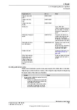
Art. no. is specified in
Clean the pinion and the pinion hole in the
motor, with
isopropanol.
Note
If the pinion is damaged the complete wrist
unit must be replaced!
3
Replacing the complete wrist unit is
detailed in section
complete wrist unit on page 258
.
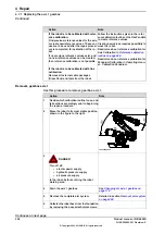
Art. no. is specified in
Apply a thin film of
mineral oil
to the pinion
shaft and the pinion hole in order to make the
pinion run smoothly and to achieve an even
friction torque when assembling the pinion.
4
Place the motor and pinion in a
press fixture
.
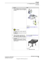
5
If the pressing force is outside the giv-
en range or if the pinion "jumps" in bit
by bit, it must be dismounted, checked,
cleaned and oiled before it is as-
sembled once again!
Press the pinion onto the new motor and check
the pressing force.
For an axis diameter of 15.5 mm, use min.
pressing force: 18.5 kN and max. pressing
force: 39.5 kN.
6
Art. no. is specified in
Measure the distance between the motor flange
and the outer surface of the pinion with the
measuring tool.
7
Modify the distance with
shims
in order to ob-
tain the same distance as measured when
dismounting the old motor (+ 0-0,05 mm).
Connect to either:
In order to release the brake, connect the 24
VDC power supply.
8
- connector R4.MP5 (in the motor):
•
+: pin 2
•
-: pin 5
- connector R3.MP5 (on the separate
cable, if not removed):
•
+: pin C
•
-: pin D
Art. no. is specified in
Fit the two
guide pins
in two of the motor attach-
ment holes.
9
Make sure the motor pinion does not
get damaged!
Fit the motor, with guidance from the pins,
making sure the motor pinion is properly mated
to the gear of axis 5.
10
4 pcs: M8 x 25; tightening torque: 24
Nm.
Secure the motor with four attachment screws
and plain washers.
11
Disconnect the brake release voltage.
12
Refit the separate cable of the axis-5 motor
and reconnect all connectors beneath the mo-
tor cover.
13
Refit the cable gland cover at the cable exit
with its two attachment screws.
14
Make sure the cover is tightly sealed!
Refit the cover on top of the motor with its four
attachment screws.
15
Detailed in the section
.
Perform a leak-down test.
16
Detailed in the section
Refit the wrist unit.
17
Continues on next page
Product manual - IRB 6650S
347
3HAC020993-001 Revision: Z
© Copyright 2004-2018 ABB. All rights reserved.
4 Repair
4.6.5 Replacement of motor, axis 5
Continued
Содержание IRB 6650S Series
Страница 1: ...ROBOTICS Product manual IRB 6650S ...
Страница 2: ...Trace back information Workspace R18 2 version a18 Checked in 2018 11 20 Skribenta version 5 3 012 ...
Страница 20: ...This page is intentionally left blank ...
Страница 50: ...This page is intentionally left blank ...
Страница 210: ...This page is intentionally left blank ...
Страница 416: ...This page is intentionally left blank ...
Страница 422: ...This page is intentionally left blank ...
Страница 426: ...This page is intentionally left blank ...
Страница 449: ......


