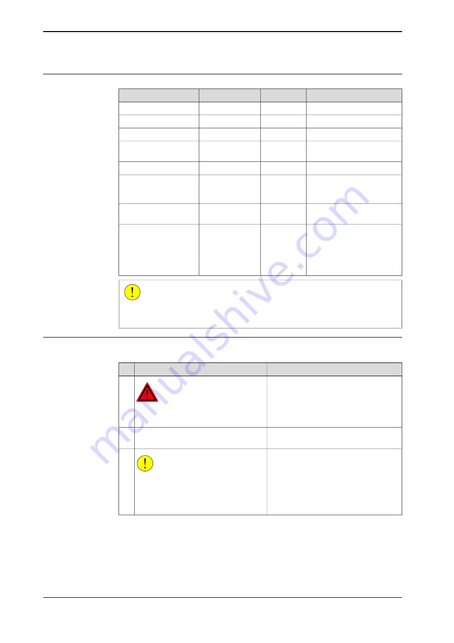
background image

Required equipment

Note

Art. no.

Spare part no.

Equipment, etc.

2400/10, /16

3HAC4796-1

Lower arm

2400L

3HAC4797-1

Lower arm

Replace if damaged.

3HAB3732-13

Sealing ring (V-ring)

Used to lubricate the sealing
ring.

3HAB3537-1

Bearing grease

-

Hoisting equipment

The content is defined in the
section

Standard tools on

page 229

.

Standard toolkit

Complete kit that also includes
operating manual.

3HAC15716-1

Calibration Pendulum
toolkit

These procedures include ref-
erences to the tools required.

Other tools and proced-
ures may be required.
See references to these
procedures in the step-
by-step instructions be-
low.

CAUTION

Always cut the paint with a knife and grind the paint edge when disassembling
parts. See

Cut the paint or surface on the robot before replacing parts on page 117

.

Removal, lower arm

The procedure below details how to remove the complete lower arm.

Note/Illustration

Action

DANGER

Turn off all electric power, hydraulic and
pneumatic pressure supplies to the robot!

1

Detailed in section

Removal, upper arm on

page 143

.

Remove the upper arm.

2

CAUTION

The robot lower arm weighs 27 kg without
any additional equipment fitted.
All lifting accessories used must be sized
accordingly!

3

Continues on next page

146

Product manual - IRB 2400

3HAC022031-001 Revision: P

© Copyright 2004-2018 ABB. All rights reserved.

4 Repair

4.5.1 Replacement of complete lower arm

Continued

Содержание IRB 2400 Series

Страница 1: ...ROBOTICS Product manual IRB 2400 ...

Страница 2: ...Trace back information Workspace R18 1 version a9 Checked in 2018 03 22 Skribenta version 5 2 025 ...

Страница 3: ...Product manual IRB 2400 L IRB 2400 10 IRB 2400 16 M2000 M2000A IRC5 Document ID 3HAC022031 001 Revision P Copyright 2004 2018 ABB All rights reserved ...

Страница 4: ...BB for losses damages to persons or property fitness for a specific purpose or the like In no event shall ABB be liable for incidental or consequential damages arising from use of this manual and products described herein This manual and parts thereof must not be reproduced or copied without ABB s written permission Keep for future reference Additional copies of this manual may be obtained from AB...

Страница 5: ...x lubricants oil or grease 41 1 4 Safety signals and symbols 41 1 4 1 Safety signals in the manual 43 1 4 2 Safety symbols on product labels 49 2 Installation and commissioning 49 2 1 Introduction 50 2 2 Unpacking 50 2 2 1 Pre installation procedure 54 2 2 2 Working range 57 2 2 3 Risk of tipping stability 58 2 3 On site installation 58 2 3 1 Lifting robot with lifting slings 59 2 3 2 Manually rel...

Страница 6: ...ete robot 120 4 3 1 Replacement of cable unit axes 1 3 126 4 3 2 Replacement of cable harness axes 4 6 134 4 4 Upper arm 134 4 4 1 Replacement of wrist IRB 2400 10 16 138 4 4 2 Replacement of wrist IRB 2400L 141 4 4 3 Replacement of complete upper arm 145 4 5 Lower arm 145 4 5 1 Replacement of complete lower arm 149 4 5 2 Replacement of tie rod 153 4 6 Frame and base 153 4 6 1 Replacement of SMB u...

Страница 7: ...n 225 7 4 Screw joints 228 7 5 Weight specifications 229 7 6 Standard tools 230 7 7 Special tools 231 7 8 Lifting equipment and lifting instructions 233 8 Spare part lists 233 8 1 Spare part lists and illustrations 235 9 Circuit diagram 235 9 1 Circuit diagrams 237 Index Product manual IRB 2400 7 3HAC022031 001 Revision P Copyright 2004 2018 ABB All rights reserved Table of contents ...

Страница 8: ...This page is intentionally left blank ...

Страница 9: ...ing any installation or service work on robot Contains general safety aspects as well as more specific information about how to avoid personal injuries and damage to the product Safety service Required information about lifting and installation of the robot Installation and commis sioning Step by step procedures that describe how to perform mainten ance of the robot Based on a maintenance schedule...

Страница 10: ...nual S4Cplus M2000A M2004 3HAC050941 001 Operating manual IRC5 with FlexPendant M2000 M2000A 3HAC7793 1 User s guide S4Cplus BaseWare OS 4 0 M2004 3HAC050944 001 Operating manual Service Information System 3HAC16578 1 Operating manual Calibration Pendulum M2000 M2000A 3HAC022907 001 Operating manual Levelmeter Calibration 3HAC042927 001 Technical reference manual Lubrication in gear boxes M2004 3H...

Страница 11: ...Safety Maintenance Maintenance schedule Interval for replacement of battery pack changed D Content updated in chapter section Decommissioning chapter added Sealing compound updated in Cut the paint or surface on the robot before replacing parts on page 117 Circuit diagrams are not included in this document but delivered as separate files See Circuit diagram on page 235 List of standards updated se...

Страница 12: ...n the robot before replacing parts on page 117 Added signal lamp G This revision includes the following updates All data about type of lubrication in gearboxes is moved from the manual to a separate lubrication manual see Type and amount of oil in gearboxes on page 92 A new SMB unit and battery is introduced with longer battery lifetime H This revision includes the following updates Added informat...

Страница 13: ...rake release board replacement procedure Corrected the replacement procedure and added replaced figures in the section Section Start of robot in cold environments on page 84 added Updated information regarding disconnecting and reconnecting battery cable to serial measurement board N Published in release R18 1 The following updates are made in this revision Added sections in General procedures on ...

Страница 14: ...ompleted with a reference to the section where the equipment is listed with further information that is article number and dimensions The designation in the procedure for the component or attachment point corresponds to the designation in the referenced list The table below shows an example of a reference to a list of required equipment from a step in a procedure Note Illustration Action Art no is...

Страница 15: ...safety standards unit conversions screw joints lists of tools Spare parts list with exploded views or references to separate spare parts lists Circuit diagrams or references to circuit diagrams Software manuals The software documentation consists of a wide range of manuals ranging from manuals for basic understanding of the operating system to manuals for entering parameters during operation A com...

Страница 16: ...erence information safety standards unit conversions screw joints lists of tools Spare parts list with corresponding figures or references to separate spare parts lists Circuit diagrams or references to circuit diagrams Technical reference manuals The technical reference manuals describe reference information for robotics products for example lubrication the RAPID language and system parameters Ap...

Страница 17: ...The manuals are aimed at those having first hand operational contact with the product that is production cell operators programmers and troubleshooters Product manual IRB 2400 17 3HAC022031 001 Revision P Copyright 2004 2018 ABB All rights reserved Product documentation IRC5 Continued ...

Страница 18: ...This page is intentionally left blank ...

Страница 19: ...arried out by in experienced or non qualified personnel Foreign objects Force majeure Nation region specific regulations To protect personnel the complete system must be designed and installed in accordance with the safety requirements set forth in the standards and regulations of the country where the robot is installed To be observed by the supplier of the complete system The integrator is respo...

Страница 20: ...eed Determine the maximum speed from the maximum velocities of the robot axes and from the position at which the robot is working in the work cell see the section Robot motion in the Product specification Also consider the maximum possible impact caused by a breaking or malfunctioning rotating tool or other device fitted to the robot Safe handling Users shall not be exposed to hazards including sl...

Страница 21: ...al parts through welding riveting or drilling of new holes into the castings The strength could be affected CAUTION Ensure that a gripper is prevented from dropping a work piece if such is used Product manual IRB 2400 21 3HAC022031 001 Revision P Copyright 2004 2018 ABB All rights reserved 1 Safety 1 1 1 Limitation of liability Continued ...

Страница 22: ...view The protective stops and emergency stops are described in the product manual for the controller 22 Product manual IRB 2400 3HAC022031 001 Revision P Copyright 2004 2018 ABB All rights reserved 1 Safety 1 1 2 Protective stop and emergency stop ...

Страница 23: ...uishing Note Use a CARBON DIOXIDE CO2 extinguisher in the event of a fire in the manipulator or controller Product manual IRB 2400 23 3HAC022031 001 Revision P Copyright 2004 2018 ABB All rights reserved 1 Safety 1 2 1 Fire extinguishing ...

Страница 24: ... may require using an overhead crane or similar equipment Increased injury Before releasing the brakes make sure that the weight of the robot does not increase the pressure on the trapped person further increasing any injury DANGER When releasing the holding brakes the robot axes may move very quickly and sometimes in unexpected ways Make sure no personnel is near or beneath the robot 24 Product m...

Страница 25: ... arrest burn injuries or other severe injuries To avoid these personal injuries switch off the main power on the controller before proceeding work Note Switch off all main power switches in a MultiMove system Product manual IRB 2400 25 3HAC022031 001 Revision P Copyright 2004 2018 ABB All rights reserved 1 Safety 1 2 3 Make sure that the main power has been switched off ...

Страница 26: ...afety lock Make sure that no one else can turn on the power to the controller and robot while you are working with the system A good method is to remove the power cable to the controller If the robot is installed at a height hanging or other than standing directly on the floor there may be additional risks than those for a robot standing directly on the floor Energy stored in the robot for the pur...

Страница 27: ...fications to the robot Connection of external safety devices Apart from the built in safety functions the robot is also supplied with an interface for the connection of external safety devices An external safety function can interact with other machines and peripheral equipment via this interface This means that control signals can act on safety signals received from the peripheral equipment as we...

Страница 28: ...y stop equipment is cor rectly installed and connected 1 How to use the hold to run function is de scribed in section How to use the hold to run function in the Operating manual IRC5 with FlexPendant Usually the hold to run function is active only in manual full speed mode To in crease safety it is also possible to activate hold to run for manual reduced speed with a system parameter 2 The hold to...

Страница 29: ...fore it is powered up 2 Verify that any safety equipment installed to secure the position or restrict the robot motion during service activity is removed 3 Verify that the fixture and work piece are well secured if applicable 4 Install all safety equipment properly 5 Make sure all personnel are standing at a safe distance from the robot and is out of its reach behind safety fences or similar 6 If ...

Страница 30: ...in USA or Canada Pay attention to the rotating axes of the robot Keep away from axes to not get entangled with hair or clothing Also be aware of any danger that may be caused by rotating tools or other devices mounted on the robot or inside the cell Keep clear of moving parts so that limbs hands or fingers do not get trapped or crushed by the robot To prevent anyone else from taking control of the...

Страница 31: ...manipulator switches to the MOTORS OFF state To ensure safe use of the teach pendant the following must be implemented The enabling device must never be rendered inoperational in any way During programming and testing the enabling device must be released as soon as there is no need for the robot to move Anyone entering the working space of the robot must always hold the teach pendant This is to pr...

Страница 32: ...lated risks IRC5 controller A danger of high voltage is associated with for example the following parts Be aware of stored electrical energy DC link Ultracapacitor bank unit in the controller Units such as I O modules can be supplied with power from an external source The main supply main switch The transformers The power unit The control power supply 230 VAC The rectifier unit 262 400 480 VAC and...

Страница 33: ...e live even if the robot system is in the OFF position Power supply cables which are in motion during the working process may be damaged Product manual IRB 2400 33 3HAC022031 001 Revision P Copyright 2004 2018 ABB All rights reserved 1 Safety 1 3 6 Risks associated with live electric parts Continued ...

Страница 34: ...e Action Wrist straps must be tested frequently to ensure that they are not damaged and are operating cor rectly Product manual IRC5 Product manual IRC5 Panel Mounted Controller Use a wrist strap The wrist strap button is located inside the control ler 1 The mat must be grounded through a current limit ing resistor Use an ESD protective floor mat 2 The mat should provide a controlled discharge of ...

Страница 35: ... your hand at some distance to feel if heat is radiating from the potentially hot component before actually touching it Wait until the potentially hot component has cooled if it is to be removed or handled in any other way Do not put anything on hot metal surfaces e g paper or plastic Product manual IRB 2400 35 3HAC022031 001 Revision P Copyright 2004 2018 ABB All rights reserved 1 Safety 1 3 8 Ho...

Страница 36: ...re must be released in the complete pneumatic or hydraulic systems before starting to repair them Work on hydraulic equipment may only be performed by persons with special knowledge and experience of hydraulics All pipes hoses and connections have to be inspected regularly for leaks and damage Damage must be repaired immediately Splashed oil may cause injury or fire Safe design Gravity may cause a...

Страница 37: ...as described below 1 Run each robot axis to a position where the combined weight of the robot arm and any load is maximized maximum static load 2 Switch the motor to the MOTORS OFF 3 Inspect and verify that the axis maintains its position If the robot does not change position as the motors are switched off then the brake function is adequate Product manual IRB 2400 37 3HAC022031 001 Revision P Cop...

Страница 38: ...losion fire may follow depending upon the circumstances Note Appropriate disposal regulations must be observed Safe handling Use safety glasses when handling the batteries In the event of leakage wear rubber gloves and chemical apron In the event of fire use self contained breathing apparatus Do not short circuit recharge puncture incinerate crush immerse force discharge or expose to temperatures ...

Страница 39: ...ion Action Description Warning Make sure that protective gear like goggles and gloves are al ways worn during this activity Changing and draining gearbox oil or grease may require hand ling hot lubricant heated up to 90 C Hot oil or grease Make sure that protective gear like goggles and gloves are al ways worn When working with gearbox lub ricant there is a risk of an allergic reaction Allergic re...

Страница 40: ... time to heat up the oil Warm oil drains quicker than cold oil Heat up the oil After filling verify that the level is correct The specified amount of oil or grease is based on the total volume of the gearbox When changing the lubricant the amount refilled may differ from the specified amount depending on how much has previously been drained from the gearbox Specified amount de pends on drained vol...

Страница 41: ...ccur if the instructions are not followed that can lead to serious injury pos sibly fatal and or great damage to the product It applies to warnings that apply to danger with for example contact with high voltage electrical units explosion or fire risk risk of poisonous gases risk of crushing impact fall from height etc WARNING xx0100000002 Warns for electrical hazards which could result in severe ...

Страница 42: ...NOTE xx0100000004 Describes where to find additional information or how to do an operation in an easier way TIP xx0100000098 42 Product manual IRB 2400 3HAC022031 001 Revision P Copyright 2004 2018 ABB All rights reserved 1 Safety 1 4 1 Safety signals in the manual Continued ...

Страница 43: ...lish German and French Symbols on safety labels Description Symbol Warning xx0900000812 Warns that an accident may occur if the instructions are not followed that can lead to serious injury possibly fatal and or great damage to the product It applies to warnings that apply to danger with for example contact with high voltage electrical units explosion or fire risk risk of poisonous gases risk of c...

Страница 44: ... Do not disassemble xx0900000815 Disassembling this part can cause injury Extended rotation xx0900000814 This axis has extended rotation working area compared to standard Brake release xx0900000808 Pressing this button will release the brakes This means that the robot arm can fall down Continues on next page 44 Product manual IRB 2400 3HAC022031 001 Revision P Copyright 2004 2018 ABB All rights re...

Страница 45: ...ip over if the bolts are not securely fastened xx1500002402 Crush xx0900000817 Risk of crush injuries Continues on next page Product manual IRB 2400 45 3HAC022031 001 Revision P Copyright 2004 2018 ABB All rights reserved 1 Safety 1 4 2 Safety symbols on product labels Continued ...

Страница 46: ...1 1 06 xx1300001087 Moving robot 1 2 3 4 5 6 xx0900000819 The robot can move unexpectedly xx1000001141 1 2 3 4 xx1500002616 Continues on next page 46 Product manual IRB 2400 3HAC022031 001 Revision P Copyright 2004 2018 ABB All rights reserved 1 Safety 1 4 2 Safety symbols on product labels Continued ...

Страница 47: ...0001242 Lifting of robot xx0900000822 Oil xx0900000823 Can be used in combination with prohibition if oil is not allowed Mechanical stop xx0900000824 Continues on next page Product manual IRB 2400 47 3HAC022031 001 Revision P Copyright 2004 2018 ABB All rights reserved 1 Safety 1 4 2 Safety symbols on product labels Continued ...

Страница 48: ...hat this part is pressurized Usually contains additional text with the pressure level Shut off with handle xx0900000827 Use the power switch on the controller Do not step xx1400002648 Warns that stepping on these parts can cause damage to the parts 48 Product manual IRB 2400 3HAC022031 001 Revision P Copyright 2004 2018 ABB All rights reserved 1 Safety 1 4 2 Safety symbols on product labels Contin...

Страница 49: ...portant that all safety information is observed There are general safety aspects that must be read through as well as more specific safety information that describes the danger and safety risks when performing the procedures Read the chapter Safety on page19 before performing any installation work Note If the IRB 2400 is connected to power always make sure that the robot is connected to protective...

Страница 50: ...he robot as specified in Weight robot on page 50 5 If the robot is not installed directly it must be stored as described in Storage condi tions robot on page 53 6 Make sure that the expected operating environment of the robot conforms to the specifications as described in Operating conditions robot on page 53 7 Before taking the robot to its installation site make sure that the site conforms to Lo...

Страница 51: ...ne Txy Bending torque in the Z plane Tz The table shows the various forces and torques working on the robot during different kinds of operation Note These forces and torques are extreme values that are rarely encountered during operation The values also never reach their maximum at the same time WARNING The robot installation is restricted to the mounting options given in following load table s Co...

Страница 52: ...00 10 16 3400 Nm Torque xy IRB 2400 L 3400 Nm IRB 2400 L 3000 Nm IRB 2400 10 16 900 Nm IRB 2400 10 16 550 Nm Torque z IRB 2400 L 900 Nm IRB 2400 L 450 Nm Requirements foundation The table shows the requirements for the foundation where the weight of the installed robot is included Note Value Requirement Flat foundations give better repeatability of the resolver calibration compared to original set...

Страница 53: ...frequencies in the region 10 20 Hz and disturbances in this region will be amplified although somewhat damped by the servo control This might be a problem depending on the requirements from the applications If this is a problem the robot needs to be isolated from the environment Storage conditions robot The table shows the allowed storage conditions for the robot Value Parameter 25 C Minimum ambie...

Страница 54: ...ositions are located at wrist center xx0200000159 Angle axis 3 Angle axis 2 Z X Pos 0 0 1620 970 0 60 0 2298 404 1 65 0 745 602 2 60 110 246 1577 3 24 5 110 403 400 4 60 100 623 1611 5 65 100 1088 115 6 Continues on next page 54 Product manual IRB 2400 3HAC022031 001 Revision P Copyright 2004 2018 ABB All rights reserved 2 Installation and commissioning 2 2 2 Working range ...

Страница 55: ...0 624 1350 5 65 100 1036 53 6 Positions in the working range The table below specifies the positions inside the working range shown in the figure above Angles º Position mm Position in figure Axis 3 Axis 2 Z X 0 0 1139 870 1 17 28 1246 510 2 31 28 722 446 3 119 60 218 515 4 Continues on next page Product manual IRB 2400 55 3HAC022031 001 Revision P Copyright 2004 2018 ABB All rights reserved 2 Ins...

Страница 56: ...figure Axis 3 Axis 2 Z X 119 85 73 607 5 26 85 210 1506 6 17 42 1148 1313 7 56 Product manual IRB 2400 3HAC022031 001 Revision P Copyright 2004 2018 ABB All rights reserved 2 Installation and commissioning 2 2 2 Working range Continued ...

Страница 57: ...vity which may cause the robot to tip over The shipping position is the most stable position Do not change the robot position before securing it to the foundation WARNING The robot is likely to be mechanically unstable if not secured to the foundation Product manual IRB 2400 57 3HAC022031 001 Revision P Copyright 2004 2018 ABB All rights reserved 2 Installation and commissioning 2 2 3 Risk of tipp...

Страница 58: ...0164 Lifting of robot Note Action If necessary release the brakes as detailed in section Manually releas ing the brakes on page 59 Move the robot to the lifting position shown in the figure above 1 Attach the straps to the special eye bolts on the gearboxes for axes 2 and 3 2 Lift the robot carefully 3 58 Product manual IRB 2400 3HAC022031 001 Revision P Copyright 2004 2018 ABB All rights reserved...

Страница 59: ... the robot axes may move very quickly and sometimes in unexpected ways Make sure no personnel is near or beneath the robot arm 1 Detailed in section Supplying power to connector R1 MP on page 60 If the robot is not connected to the controller power must be supplied to the connector R1 MP 2 xx0600002697 The internal brake release unit is located at the base of the robot and equipped with but tons f...

Страница 60: ...V pins If they are mixed up damage can be caused to a resistor diode and to the system board 1 xx0200000167 Connect an external power supply to connector R1 MP at the robot base Supply 24 V on pin B8 0 V on pin C10 2 Release the brakes with the brake release unit as detailed in the previous procedure 3 60 Product manual IRB 2400 3HAC022031 001 Revision P Copyright 2004 2018 ABB All rights reserved...

Страница 61: ...hstand the stress loads defined in section Pre installation procedure on page 50 Note When the robot is to be mounted in a tilted or a suspended position the guide sleeves must be used to secure the bolted joint Attachment screws The table below specifies the type of securing screws and washers to be used for securing the robot to the base plate foundation M16 x 50 Suitable screws lightly lubricat...

Страница 62: ...2x 48 20 Ø 0 25 D 35 H8 2x 0 039 0 A A xx1400002065 Guide sleeves Two guide sleeves can be fitted to the two rear bolt holes to allow the same robot to be remounted without re adjusting the program Art no Equipment 2151 0024 169 Guide sleeves 62 Product manual IRB 2400 3HAC022031 001 Revision P Copyright 2004 2018 ABB All rights reserved 2 Installation and commissioning 2 3 3 Orienting and securin...

Страница 63: ...tem parameters for a suspended or tilted robot on page 67 Turning the robot 1 Use the special tool for inverted mounting see following figure xx0200000212 Lifting beam A Fork lift B Inverted mounting tool 3HAB8961 1 Continues on next page Product manual IRB 2400 63 3HAC022031 001 Revision P Copyright 2004 2018 ABB All rights reserved 2 Installation and commissioning 2 3 4 Mounting the robot in sus...

Страница 64: ...astic plugs see following figure xx0200000215 Plastic plugs x8 A 64 Product manual IRB 2400 3HAC022031 001 Revision P Copyright 2004 2018 ABB All rights reserved 2 Installation and commissioning 2 3 4 Mounting the robot in suspended position Continued ...

Страница 65: ...oad diagrams permitted extra loads equipment and their positions are specified in the product specification The loads must be defined in the software User s guide S4Cplus BaseWare OS 4 0 Operating manual IRC5 with FlexPendant Stopping time and braking distances The performance of the motor brake depends on if there are any loads attached to the robot For more information see product specification ...

Страница 66: ...on delivered with the signal lamp Function The lamp is active in MOTORS ON mode Further information Further information about the MOTORS ON MOTORS OFF mode may be found in the product manual for the controller 66 Product manual IRB 2400 3HAC022031 001 Revision P Copyright 2004 2018 ABB All rights reserved 2 Installation and commissioning 2 3 6 Signal lamp option ...

Страница 67: ...e mounting angle must be configured correctly in the system parameters so that the robot system can control the movements in the best possible way An incorrect definition of the mounting angle will result in Overloading the mechanical structure Lower path performance and path accuracy Some functions will not work properly for example Load Identification and Collision detection Gravity Beta If the ...

Страница 68: ...n the system parameter 7 axes high performance motion is set see Technical reference manual System parameters Gamma Rotation Gamma Rotation defines the orientation of the robot foot on the travel carriage track motion Mounting angles and values The parameter Gravity Beta or Gravity Alpha specifies the mounting angle of the robot in radians It is calculated in the following way Gravity Beta A x 3 1...

Страница 69: ...s 0 0 Floor mounted 1 0 785398 45 Tilted 2 1 570796 90 Wall 3 1 570796 90 Wall 4 Note For suspended robots 180 it is recommended to use Gravity Beta instead of Gravity Alpha Continues on next page Product manual IRB 2400 69 3HAC022031 001 Revision P Copyright 2004 2018 ABB All rights reserved 2 Installation and commissioning 2 3 7 Setting the system parameters for a suspended or tilted robot Conti...

Страница 70: ...angle must be redefined when changing the mounting angle of the robot The parameters belong to the type Robot in the topic Motion How to calculate a new value is detailed in Mounting angles and values on page68 The system parameters are described in Technical reference manual System parameters The system parameters are redefined in the Configuration Editor in RobotStudio or on the FlexPendant 70 P...

Страница 71: ... Axis 1 hardware mechanical stop and position switch Axis 2 hardware mechanical stop Axis 3 hardware limit switch This section describes how to install hardware that restricts the working range Note Adjustments must also be made in the robot configuration software system parameters References to relevant manuals are included in the installation procedures Product manual IRB 2400 71 3HAC022031 001 ...

Страница 72: ...as shown in the figure below The restrictions are made by fitting two extra stops to the robot base and adjusting the system parameter configuration xx0500002105 Continues on next page 72 Product manual IRB 2400 3HAC022031 001 Revision P Copyright 2004 2018 ABB All rights reserved 2 Installation and commissioning 2 4 2 Mechanically restricting the working range of axis 1 ...

Страница 73: ...r s guide S4Cplus BaseWare OS 4 0 RobotWare 4 0 Technical reference manual System parameters Fitting mechanical stop axis 1 The procedure below details how to fit a mechanical stop to the robot base Note Action Decide where to fit the extra mechanical stops according to the figure Location of where to drill holes for extra stops on page 75 1 The template is also shown in the figure Drill template ...

Страница 74: ...ment in RobotWare 4 0 is detailed in User s guide S4Cplus BaseWare OS 4 0 chapter System Parameters topic Manipulator Adjust the software working range limitations system parameter configuration to correspond to the mechanical limitations 8 The system parameters that must be changed Upper joint bound and Lower joint bound are described in Technical reference manual System parameters WARNING If the...

Страница 75: ... This mounting direction only D The minimum and maximum measurement between the mechanical stops The difference between the measurement and the minimum and maximum working range is 2 x 4º which corresponds to the width of the stop pin at the frame Continues on next page Product manual IRB 2400 75 3HAC022031 001 Revision P Copyright 2004 2018 ABB All rights reserved 2 Installation and commissioning...

Страница 76: ...inside this sector C Center lines for the hidden stiffening ribs D Continues on next page 76 Product manual IRB 2400 3HAC022031 001 Revision P Copyright 2004 2018 ABB All rights reserved 2 Installation and commissioning 2 4 2 Mechanically restricting the working range of axis 1 Continued ...

Страница 77: ...te xx0200000207 Product manual IRB 2400 77 3HAC022031 001 Revision P Copyright 2004 2018 ABB All rights reserved 2 Installation and commissioning 2 4 2 Mechanically restricting the working range of axis 1 Continued ...

Страница 78: ...are specified in the following table xx0200000208 Qty item 3 Qty item 2 Qty item 1 Working range 110 100 2 2 1 110 70 4 2 2 110 40 2 2 1 80 100 4 2 2 80 70 6 2 3 80 40 4 2 2 50 100 6 2 3 50 70 8 2 4 50 40 6 2 3 20 100 8 2 4 20 70 10 2 5 20 40 Required equipment Note Art no Equipment 3HAC 2624 1 Stop axis 2 Continues on next page 78 Product manual IRB 2400 3HAC022031 001 Revision P Copyright 2004 2...

Страница 79: ... Technical reference manual System parameters The content is defined in the section Standard tools on page 229 Standard toolkit Product manual IRB 2400 79 3HAC022031 001 Revision P Copyright 2004 2018 ABB All rights reserved 2 Installation and commissioning 2 4 3 Mechanically restricting the working range of axis 2 Continued ...

Страница 80: ...enses the position via a cam The system parameter configuration must also be updated Mounting of eletrical stop Following illustration shows how to fit the electrical stop xx0200000211 80 Product manual IRB 2400 3HAC022031 001 Revision P Copyright 2004 2018 ABB All rights reserved 2 Installation and commissioning 2 4 4 Installation of limit switch axis 3 ...

Страница 81: ...e robot The figure below shows all connections of the robot cabling including the customer connections xx0500002043 Product manual IRB 2400 81 3HAC022031 001 Revision P Copyright 2004 2018 ABB All rights reserved 2 Installation and commissioning 2 5 1 Connectors on robot ...

Страница 82: ... to and control of the external axes motors as well as feedback from the servo system External axes cables option See the Application manual Additional axes and stand alone controller M2004 or Application manual External axes M2000 1 Art no is specified in section References on page 10 1 The cable categories are divided into sub categories specified below Robot cables These cables are included in ...

Страница 83: ... included in the delivery if the position switch option is ordered The position switches can also be ordered without cables The cables are completely pre manufactured and ready to plug in Cabling between robot base and controller Connection point cabinet Connection point robot Art no Cable XS8 R1 SW 3HAC7997 1 Position switch cable axis 1 7 m XS8 R1 SW 3HAC7997 2 Position switch cable axis 1 15 m ...

Страница 84: ...regulated with the RAPID instruction VelSet Start the robot with its normal program but with reduced speed 1 Adjusting the speed and acceleration during warm up Depending on how cold the environment is and what program is being used the speed might need to be ramped up until reached maximum The table shows examples of how to adjust the speed Speed velocity AccSet Work cycles v100 100 mm s 20 20 3 ...

Страница 85: ... sections and divided according to the maintenance activity Safety information Observe all safety information before conducting any service work There are general safety aspects that must be read through as well as more specific safety information that describes the danger and safety risks when performing the procedures Read the chapter Safety on page 19 before performing any service work Note If ...

Страница 86: ...ing means more frequent maintenance activities SIS specified by the robot s SIS Service Information System A typical value is given for a typical work cycle but the value will differ depending on how hard each part is run The SIS used in M2000 and M2000A is further described in the section Service Information System M2000 on page 103 The SIS used in M2004 is further described in the Operating manu...

Страница 87: ...U102 3 pole battery contact 36 months or battery low alert iv Replacement of battery pack SMB unit Replace if damaged 36 months Inspection of all signal cabling in lower and up per arm Fitting mechanical stop axis 1 on page 73 Replace if bent 60 months Replacement of mechan ical stop axis 1 i Change the oil for the first time after 4000 hours then after every 60 months ii Changing interval if the ...

Страница 88: ...ase unit A Warning sign Heat 3 pcs B Rating label C Calibration label 4 pcs D ABB logotype 2 pcs E Protection class logotype F Warning sign Symbol of flash 5 pcs G UL UR label H Instruction plate Lifting of robot J Designation sign K Information sign AbsAcc L Continues on next page 88 Product manual IRB 2400 3HAC022031 001 Revision P Copyright 2004 2018 ABB All rights reserved 3 Maintenance 3 3 1 ...

Страница 89: ...t Note Action DANGER Turn off all electric power supply hydraulic pressure supply air pressure supply to the robot before entering the robot work ing area 1 See the figure in Location of information labels on page 88 Check all labels 2 Replace any missing or damaged labels 3 Product manual IRB 2400 89 3HAC022031 001 Revision P Copyright 2004 2018 ABB All rights reserved 3 Maintenance 3 3 1 Inspect...

Страница 90: ...erences to the tools required Other tools and procedures may be required See references to these procedures in the step by step instructions below CAUTION Always cut the paint with a knife and grind the paint edge when disassembling parts See Cut the paint or surface on the robot before replacing parts on page117 Inspecting signal lamp Use this procedure to inspect the function of the signal lamp ...

Страница 91: ...ble connections 5 24V Measure the voltage in connectors motor axis 3 6 Check the cabling If a fault is detected re place 7 Seal and paint the joints that have been opened Also repair possible damages of the special Foundry Prime paint coat of the robot See Cut the paint or surface on the robot be fore replacing parts on page 117 Note After all repair work wipe the robot free from particles with sp...

Страница 92: ... changing activities of lubrication always contact the local ABB Service organization for more information For ABB personnel Always check ABB Library for the latest revision of the manual Technical reference manual Lubrication in gearboxes in order to always get the latest information of updates about lubrication in gearboxes A new revision will be published on ABB Library immediately after update...

Страница 93: ...bout the oil is found in Technical reference manual Lubrication in gearboxes Lubricating oil See Type and amount of oil in gearboxes on page 92 The capacity of the vessel must be suffi cient to take the complete amount of oil Oil collecting vessel The content is defined in the section Standard tools on page 229 Standard toolkit Continues on next page Product manual IRB 2400 93 3HAC022031 001 Revis...

Страница 94: ...d the safety information in the section Safety risks during work with gearbox lubricants oil or grease on page 39 2 xx1600000098 Run the upper arm to a horizontal position and turn axis 4 to the calibration position 3 Turn axis 4 through 180 so that the oil plug A on the tilt housing is pointing downwards 4 Shown in the figure Location of oil plugs axes 5 6 IRB 2400L 5 on page 93 Remove oil plugs ...

Страница 95: ... the calibration position 3 Shown in the figure Location of oil plugs axes 5 6 IRB 2400 10 16 on page 93 Remove the oil plugs in the wrist 4 xx0300000121 Turn axis 4 through 90 so that the oil plug on the side of the wrist is pointing downwards 5 Then turn axis 4 another 90 6 Let the remaining oil run out through the hole on the tilt housing 7 Refilling gearbox axes 5 6 The procedure below details...

Страница 96: ... plug hole A located on the tilt housing axis 5 until the oil reaches up to oil plug B in the front of the wrist Valid for IRB 2400 10 16 kg 5 Fill oil in the plug hole A located on the tilt housing axis 5 until the oil reaches up to the hole located on the side of the wrist Note If the robot is mounted in suspension the wrist should be turned 180 6 Refit the oil plugs to the wrist 7 96 Product ma...

Страница 97: ...ocation of SMB battery unit The SMB battery unit is located inside the robot base as shown in the figure below SMB connection A SMB battery RMU B SMB battery connector C Required equipment Note There are two variants of SMB units and batteries One with 2 pole battery contact and one with 3 pole battery contact The battery with the 3 pole contact has a longer lifetime It is important that the SMB u...

Страница 98: ...nit please read the safety information in the section The unit is sensitive to ESD on page 34 Remove the rear cover plate A on the robot by unscrewing its attachment screws B CAUTION Clean cover from metal residues before opening Metal residues can cause shortage on the boards which can result in hazardous failures 3 Remove the battery terminals from the serial measuring board and cut the clasp th...

Страница 99: ...tion Updating revolu tion counters on page 210 Update the revolution counters 7 Product manual IRB 2400 99 3HAC022031 001 Revision P Copyright 2004 2018 ABB All rights reserved 3 Maintenance 3 4 3 Replacement of SMB battery Continued ...

Страница 100: ... on page 88 2 Write down the oil level 3 Inspect the oil level again after for example 6 months 4 If the oil level is decreased then replace the gearbox Oil spills discolors painted surfaces Oil spills on painted surfaces of the robot can result in discoloration Note After all repair and maintenance work involving oil always wipe the robot clean from all surplus oil Special cleaning considerations...

Страница 101: ...s a rust prevention solution Yes With light cleaning deter gent or spirit Yes Wash It is highly recommended that the water and steam contains rust preventive without cleaning deter gents No No Yes With light cleaning deter gent spirit or isopropyl alco hol Yes Clean room i Perform according to section Cleaning with water and steam on page 101 ii Perform according to section Cleaning with water and...

Страница 102: ...sed min 45 spread Minimum distance from nozzle to encapsulation 0 4 meters Maximum water temperature 80 C Cables Movable cables need to be able to move freely Remove waste material such as sand dust and chips if it prevents cable movement Clean the cables if they have a crusty surface for example from dry release agents 2 See Cleaning methods on page 101 for exceptions 102 Product manual IRB 2400 ...

Страница 103: ...ine what values are adequate and suit able for your application in your production environment 2 How to do this is detailed in Setting the SIS parameters on page 108 Enter these parameters in the system 3 Run the robot in normal operation 4 The TPU displays for resetting any SIS value are shown in Description of Service Information System SIS on page 104 Reset the counter if a repair is made or if...

Страница 104: ...on percentage of the axis 6 gearbox service interval Counters are reset when maintenance has been performed The counter status is displayed after running the service routine for maintenance Status OK indicates that no service interval limit has been exceeded by that counter Calendar time This is a clock within the control system that keeps track of the service interval based on calendar time When ...

Страница 105: ...109 The following information is available about the joint service status in the service routine Service status for axis x i e the automatically calculated time parameter has not been exceeded Joint x OK The service interval for the axis in question has been reached Joint x NOK No service time parameter calculation available Joint x N A Applies to axes 4 and 5 IRB 6600 and IRB 7600 The following i...

Страница 106: ...ction made a message No data available is displayed when trying to display the data 106 Product manual IRB 2400 3HAC022031 001 Revision P Copyright 2004 2018 ABB All rights reserved 3 Maintenance 3 6 2 Description of Service Information System SIS Continued ...

Страница 107: ...rs selected as service interval E g by setting the value 2 the SIS will save this as the nominal time for activating the alarm not counting the percentage described below Calendar time warning A percentage of the Calendar time limit specified above E g by setting the value 90 the SIS will alert the operator after 90 of two years i e 657 days after a calendar time Reset was made the last time Gearb...

Страница 108: ...m parameters using the TPU 1 Go to System paramet ers Manipulator types 2 2 Select 0 SIS parameters and press Enter 3 Select the required system The parameter list is dis played 4 Available parameters are described in section SIS system parameters on page 107 Select the required paramet ers by stepping up and down through the parameter list 5 108 Product manual IRB 2400 3HAC022031 001 Revision P C...

Страница 109: ...mit is detailed in section Setting the SIS parameters on page 108 Service Message Service is due X production hours since last service Operation time Proceed with the required service as detailed in chapter Repair on page111 or chapter Maintenance on page 85 depending on which type of service X number of operation hours remain until the manually set operation time limit expires Service Message X p...

Страница 110: ...eration hours since the system was started Corresponds to the oper ating time counter on the control cabinet Operation time seconds sisTotRunT The number of operation hours since start last reset of the operation time counter Corres ponds to the operating time counter on the control cabinet Operation time seconds sisRunT Estimated life of gearbox axis 1 Gearbox time hours sisL10h_1 Operation time ...

Страница 111: ...fic repair activity are listed in the respective procedures The details of equipments are also available in different lists in the chapter References on page 10 Safety information There are general safety information and specific safety information The specific safety information describes the danger and safety risks while performing specific steps in a procedure Make sure to read through the chap...

Страница 112: ...he pressure must under no circumstance be higher than 0 25 bar 20 25 kPa Also during the time when the pressure is raised 3 0 2 0 25 bar 20 25 kPa Disconnect the compressed air supply 4 If the compressed air is signific antly colder or warmer than the gearbox to be tested a slight pressure increase or decrease may occur This is quite normal Wait for approximately 8 10 minutes and make sure that no...

Страница 113: ...o any stresses during the assembly work 3 Assembly of tapered bearings Follow the preceding instructions for the assembly of the bearings when mounting a tapered bearing on the robot In addition to those instructions the following procedure must be carried out to enable the roller elements to adjust to the correct position against the race flange Note Action Tension the bearing gradually until the...

Страница 114: ...arted During operation the bearing should be filled to 70 80 of the available volume Ensure that grease is handled and stored properly to avoid contamination Grease the different types of bearings as following description Grooved ball bearings must be filled with grease from both sides Tapered roller bearings and axial needle bearings must be greased in the split condition 114 Product manual IRB 2...

Страница 115: ... of the correct type provided with cutting edge There is no damage to the sealing edge feel with a fingernail 1 Inspect the sealing surface before mounting If scratches or damage are found the seal must be replaced since it may result in future leakage 2 Article number is specified in Equipment on page115 Lubricate the seal with grease just before fitting Not too early there is a risk of dirt and ...

Страница 116: ...ly when fastening the flange joint 4 O rings The following procedure describes how to fit o rings Note Action Ensure that the correct o ring size is used 1 Defective o rings including damaged or deformed o rings may not be used Check the o ring for surface defects burrs shape accuracy or deformation 2 Defective o rings may not be used Check the o ring grooves 3 The grooves must be geometrically co...

Страница 117: ...g agent Knife Lint free cloth 3HAC036639 001 Touch up paint Clean Room White 3HAC037052 001 Touch up paint Standard Foundry Plus ABB Orange Removing Description Action xx0900000121 Cut the paint with a knife in the joint between the part that will be removed and the struc ture to avoid that the paint cracks 1 Carefully grind the paint edge that is left on the structure to a smooth surface 2 Refitt...

Страница 118: ...Use Touch up paint Clean Room white to paint the joint Note Always read the instruction in the product data sheet in the paint repair kit for Clean Room 6 Note After all repair work wipe the robot free from particles with spirit on a lint free cloth 118 Product manual IRB 2400 3HAC022031 001 Revision P Copyright 2004 2018 ABB All rights reserved 4 Repair 4 2 4 Cut the paint or surface on the robot...

Страница 119: ...e to the robot Elimination To eliminate the danger after service work has been performed inside the SMB recess follow the procedure below Action Make sure the power is turned off 1 Remove the push button guard if necessary 2 Verify that the push buttons of the brake release unit are working by pressing them down one by one 3 Make sure none of the buttons are jammed in the tube If a button gets jam...

Страница 120: ...s xx0500002541 Connectors behind the cover plate at the robot base R1 MP1 3 and R2 BU1 3 At the serial measurement board R2 G battery R2 FB1 3 A Connectors at motor 2 R3 MP2 and R3 FB2 B Connectors at motor 3 R3 MP3 R3 FB3 R3 LS1 and R3 LS2 C Connectors at motor 1 R3 MP1 R3 FB1 D Upper bracket E Cable guide in the middle of the frame F Continues on next page 120 Product manual IRB 2400 3HAC022031 ...

Страница 121: ...e pro cedures in the step by step instructions below CAUTION Always cut the paint with a knife and grind the paint edge when disassembling parts See Cut the paint or surface on the robot before replacing parts on page117 Removal cable unit axes 1 3 The procedure below details how to remove the cabling of axes 1 3 Note Illustration Action Axes 2 and 3 may be tilted slightly to im prove access In or...

Страница 122: ...FB 1 3 from the connection R2 SMB1 4 on the SMB unit 7 This releases the cable harness from the frame Unscrew the four screws securing the cable gland 8 xx0200000404 Remove the cable guide in the middle of the frame by removing the attachment screws of the holder A Remove the cables from the guide 9 Note Different robot versions are fitted with different versions of the holder Make sure the correc...

Страница 123: ...ess through the center hole of axis 1 2 The gasket is included in the spare part of the cable unit spare part no is spe cified in Required equipment on page 121 Fit a new gasket and fit the connection box on motor 1 2 and 3 using the three attach ment screws 3 xx0200000401 Reconnect all the connectors at motors 1 2 and 3 4 R3 MP1 3 R3 FB1 3 Connection box Refit the cover of the motors axes 1 2 and...

Страница 124: ...ps Note Always use a new sealing combined with a flange sealing Loctite 574 8 Art numbers are specified in Required equipment on page 121 Connect the connectors R2 FB 1 3 to the connection R2 SMB1 4 on the SMB unit 9 Note The cable between the battery and the SMB unit may stay connected in order to avoid recalibration of the robot Refit the SMB unit to the bracket with the nuts Be careful not to l...

Страница 125: ...rs on page 210 If the battery has been disconnected from the SMB unit the revolution counters must be updated 14 DANGER Make sure all safety requirements are met when performing the first test run These are further detailed in the section First test run may cause injury or damage on page 29 15 Product manual IRB 2400 125 3HAC022031 001 Revision P Copyright 2004 2018 ABB All rights reserved 4 Repai...

Страница 126: ... R2 FB1 3 and R2 FB4 6 a2 Connectors at motor 2 R3 MP2 and R3 FB2 B Connectors at motor 3 R3 MP3 R3 FB3 R3 LS1 and R3 LS2 C Connectors at motor 1 R3 MP1 R3 FB1 D Connectors at motor 4 5 kg option R3 MP4 and R3 FB4 E Connectors at motor 4 15 kg option R3 MP4 and R3 FB4 e Connectors at motor 5 R3 MP5 and R3 FB5 F Connectors at motor 6 R3 MP6 and R3 FB6 G Connectors R3 H1 and R3 H2 5 kg option H Conn...

Страница 127: ...cedures in the step by step instruc tions below CAUTION Always cut the paint with a knife and grind the paint edge when disassembling parts See Cut the paint or surface on the robot before replacing parts on page117 Removal cable harness axes 4 6 The procedure below details how to remove the cable harness axes 4 6 Note Illustration Action DANGER Turn off all electric power hydraulic and pneumatic ...

Страница 128: ...able In order to remove the SMB unit com pletely the connector R2 G must be discon nected This causes a necessary recalibra tion of the robot Disconnect connector R2 FB 4 6 from the connection R2 SMB4 6 on the SMB unit 7 This releases the cable harness from the frame Unscrew the four screws securing the cable gland 8 xx0200000404 Remove the adapter plate from the harness by removing its two attach...

Страница 129: ...6 C R3 MP4 D R3 FB5 E R3 FB6 F R3 FB4 12 Remove all screws holding the motor case on motor 4 6 13 Gently pull the cable harness out 14 Refitting cable harness axes 4 6 The procedure below details how to refit the cable harness axes 4 6 Note Illustration Action DANGER Turn off all electric power hydraulic and pneumatic pressure supplies to the ro bot 1 Continues on next page Product manual IRB 2400...

Страница 130: ...tly pull down the cable harness through the center of the lower arm and through the hole of axis 1 3 Note Always use a new gasket Art no is specified in Required equipment on page127 Fit a new gasket and fit the motor case on motor 4 6 using the nine torx screws 4 Continues on next page 130 Product manual IRB 2400 3HAC022031 001 Revision P Copyright 2004 2018 ABB All rights reserved 4 Repair 4 3 2...

Страница 131: ...3 B A R3 MP5 B R3 MP6 C R3 MP4 D R3 FB5 E R3 FB6 F R3 FB4 5 xx0300000063 xx0300000062 Fit the back cover of the motors 4 6 6 Continues on next page Product manual IRB 2400 131 3HAC022031 001 Revision P Copyright 2004 2018 ABB All rights reserved 4 Repair 4 3 2 Replacement of cable harness axes 4 6 Continued ...

Страница 132: ...t entry will not be watertight Note Always use a new sealing and combine it with a flange sealing Loctite 574 9 Art no s are specified in Required equipment on page 127 Connect connectors R2 FB 4 6 to the connection R2 SMB4 6 on the SMB unit 10 Note The cable between the battery and the SMB unit may stay connected in order to avoid recalibration of the robot Fit the SMB unit to the bracket with th...

Страница 133: ...e all safety requirements are met when performing the first test run These are further detailed in the section First test run may cause injury or dam age on page 29 15 Product manual IRB 2400 133 3HAC022031 001 Revision P Copyright 2004 2018 ABB All rights reserved 4 Repair 4 3 2 Replacement of cable harness axes 4 6 Continued ...

Страница 134: ...e axis 5 and 6 of the robot This is shown in pos A in the figure below xx0300000103 Wrist A Upper arm B Lower arm C Frame D Base E Continues on next page 134 Product manual IRB 2400 3HAC022031 001 Revision P Copyright 2004 2018 ABB All rights reserved 4 Repair 4 4 1 Replacement of wrist IRB 2400 10 16 ...

Страница 135: ...7 1 Measuring tool 24 VDC 1 5 A Power supply For releasing the brakes The content is defined in the section Standard tools on page 229 Standard toolkit These procedures include references to the tools re quired Other tools and procedures may be required See refer ences to these procedures in the step by step instruc tions below Continues on next page Product manual IRB 2400 135 3HAC022031 001 Revi...

Страница 136: ...e wrist 3 Refitting wrist unit The wrist which includes axes 5 and 6 is a complete unit comprising drive units and gearboxes It is a replacement unit of complex design and should not normally be serviced on site Instead it should be sent to ABB for service The procedure below details how to refitt the wrist to the robot upper arm Note Illustration Action DANGER Turn off all electric power hydrauli...

Страница 137: ...t of motors axes 4 6 IRB 2400 10 16 on page 190 8 A Gears on drive shaft unit axis 5 6 B Gears on the wrist Tightening torque 17 Nm Tighten the attachment screws and washers 9 Check the play by moving axes 5 and 6 by hand 10 This is detailed in section Oil change gearbox axes 5 6 wrist unit on page 93 Refill the wrist unit with oil 11 Calibration is detailed in a separ ate calibration manual enclo...

Страница 138: ...s 5 and 6 of the robot and shown in pos A in the figure below xx0200000409 Wrist A Upper arm B Lower arm C Frame D Base E Continues on next page 138 Product manual IRB 2400 3HAC022031 001 Revision P Copyright 2004 2018 ABB All rights reserved 4 Repair 4 4 2 Replacement of wrist IRB 2400L ...

Страница 139: ...wrist from the robot upper arm The wrist which includes axes 5 and 6 is a complete unit comprising drive units and gearboxes It is a replacement unit of complex design and should not normally be serviced on site Instead it should be sent to ABB for service etc ABB recommends its customers to carry out only the following servicing and repair work on the wrist Note Illustration Action DANGER Turn of...

Страница 140: ...5 Refit the plugs 6 Refit the cover at the motor side of axis 5 6 7 Calibration is detailed in a separate calibration manual enclosed with the calibration tools Calibrate the robot 8 General calibration information is included in the section Calibration information on page 205 DANGER Make sure all safety requirements are met when performing the first test run These are further detailed in the sect...

Страница 141: ...B the figure below The complete upper arm includes the wrist unit xx0200000409 Wrist axis 5 6 A Upper arm axis 3 4 B Lower arm axis 2 C Frame axis 1 D Base E Continues on next page Product manual IRB 2400 141 3HAC022031 001 Revision P Copyright 2004 2018 ABB All rights reserved 4 Repair 4 4 3 Replacement of complete upper arm ...

Страница 142: ...er tools and procedures may be required See references to these procedures in the step by step instructions below CAUTION Always cut the paint with a knife and grind the paint edge when disassembling parts See Cut the paint or surface on the robot before replacing parts on page117 Upper arm attachment xx0200000436 Cover A KM nuts B Attachment screw C Sealing insert a strap under the sealing to let...

Страница 143: ... 7 xx0200000435 Fit the lifting device to the upper arm and lift enough for the strap to stretch without lifting the robot 8 Lifting without lifting tool Art no is specified in Required equipment on page 142 Pull out the shaft using the dismounting tool for shaft ends Mark the shafts left right 9 Refitting upper arm The procedure below details how to refit the complete upper arm Note Action DANGER...

Страница 144: ...y Unscrew the nut again Tighten the KM nut with a torque of 35 Nm Push in a strap under the sealing to let the air go out and then fit the covers 7 Fit the calibration plate for axis 3 8 Reconnect the connection boxes and the cabling 9 Calibration is detailed in a separ ate calibration manual enclosed with the calibration tools Recalibrate the robot 10 General calibration information is included i...

Страница 145: ...ore detailed view of the component and its position may be found in chapter Spare part lists on page 233 xx0200000409 Wrist A Upper arm B Lower arm C Frame D Base E Continues on next page Product manual IRB 2400 145 3HAC022031 001 Revision P Copyright 2004 2018 ABB All rights reserved 4 Repair 4 5 1 Replacement of complete lower arm ...

Страница 146: ... instructions be low CAUTION Always cut the paint with a knife and grind the paint edge when disassembling parts See Cut the paint or surface on the robot before replacing parts on page117 Removal lower arm The procedure below details how to remove the complete lower arm Note Illustration Action DANGER Turn off all electric power hydraulic and pneumatic pressure supplies to the robot 1 Detailed in...

Страница 147: ...on page 165 Remove the parallel arm 6 Pull down the cabling from inside the lower arm and remove any cable attach ments 7 xx0200000440 Remove the attachment screws and the spring tension plate 8 Attachment screws Remove the lower arm 9 Continues on next page Product manual IRB 2400 147 3HAC022031 001 Revision P Copyright 2004 2018 ABB All rights reserved 4 Repair 4 5 1 Replacement of complete lowe...

Страница 148: ... plate to the lower arm and secure the arm to the gearbox with the 12 attachment screws 6 Detailed in section Refitting parallel arm on page 166 Refit the parallel arm 7 Detailed in section Refitting tie rod on page 151 Refit the tie rod 8 Detailed in section Refitting upper arm on page 143 Refit the upper arm 9 Detailed in section Refitting cable harness axes 4 6 on page 129 Refit the cabling 10 ...

Страница 149: ... more detailed view of the component and its position may be found in chapter Spare part lists on page 233 xx0200000444 Tie rod A Parallel arm B Continues on next page Product manual IRB 2400 149 3HAC022031 001 Revision P Copyright 2004 2018 ABB All rights reserved 4 Repair 4 5 2 Replacement of tie rod ...

Страница 150: ...o Spare part no Equipment etc Loctite 243 3HAB7116 1 Locking liquid 3HAB3537 1 Grease 3HAB6324 1 Press tool parallel bar bearing Used to fit the tie rod 3HAB6331 1 Mounting tool parallel bar The content is defined in the section Standard tools on page 229 Standard toolkit Continues on next page 150 Product manual IRB 2400 3HAC022031 001 Revision P Copyright 2004 2018 ABB All rights reserved 4 Repa...

Страница 151: ...equipment fitted All lifting accessories used must be sized accord ingly 2 Shown in the figure Location of tie rod on page 149 Use a crane to secure the weight of the upper arm 3 Shown in the figure Location of tie rod on page 149 Remove the attachment screw from the upper and lower end 4 Shown in the figure Location of tie rod on page 149 Remove the locking washer from both ends 5 M8 Insert a scr...

Страница 152: ...ng sealings to the bearings 6 Shown in the figure Location of tie rod on page 149 Refit the back up ring 7 Shown in the figure Location of tie rod on page 149 Refit the locking washer 8 M8 x 16 Refit the attachment screw at both ends of the bar using locking liquid 9 Loctite 243 Shown in the figure Location of tie rod on page 149 Calibration is detailed in a separate calib ration manual enclosed w...

Страница 153: ...of the component and its position may be found in chapter Spare part lists on page 233 Note that the robot is shown with the SMB cover already removed A B C xx1300000289 SMB battery cable A SMB battery RMU 3 pole battery contact B SMB unit RMU 101 C Continues on next page Product manual IRB 2400 153 3HAC022031 001 Revision P Copyright 2004 2018 ABB All rights reserved 4 Repair 4 6 1 Replacement of...

Страница 154: ...AC044168 001 and battery pack 3HAC44075 001 3HAC046277 001 Serial measurement unit The content is defined in the section Standard tools on page 229 Standard toolkit See the chapter Circuit dia gram on page 235 Circuit diagram These procedures include references to the tools re quired Other tools and proced ures may be required See references to these proced ures in the step by step instructions be...

Страница 155: ... SMB1 3 B Connector R2 SMB1 2 external axis C Connector R2 SMB D Connector R2 G battery unit E Continues on next page Product manual IRB 2400 155 3HAC022031 001 Revision P Copyright 2004 2018 ABB All rights reserved 4 Repair 4 6 1 Replacement of SMB unit Continued ...

Страница 156: ...e Action DANGER Turn off all electric power hydraulic and pneumatic pressure supplies to the robot 1 ELECTROSTATIC DISCHARGE ESD The unit is sensitive to ESD Before handling the unit read the safety information in section The unit is sensitive to ESD on page 34 2 Continues on next page 156 Product manual IRB 2400 3HAC022031 001 Revision P Copyright 2004 2018 ABB All rights reserved 4 Repair 4 6 1 ...

Страница 157: ... battery 4 Remove the SMB cover by unscrewing its at tachment screws 5 Pull the battery cable through the hole in the SMB cover Remove the two locknuts and washers from the pins securing the board 6 xx1700000993 Disconnect the battery cable by pressing down the upper lip of the R2 G connector to release the lock while pulling the connector upwards 7 Continues on next page Product manual IRB 2400 1...

Страница 158: ...Refit the SMB cover using the attachment lock nuts 10 Pull the battery cable through the hole in the SMB cover Reassemble the two locknuts and washers to the pins securing the board 11 Refit the SMB battery 12 Always replace a removed gasket with a new Fit a new gasket to the cover and refit the cover with the attachment screws 13 Art no is specified in Required equip ment on page 154 Detailed in ...

Страница 159: ...the base cover at the robot base as shown below C B A xx1700001192 Base cover A Push button guard B Brake release unit located inside the base C Continues on next page Product manual IRB 2400 159 3HAC022031 001 Revision P Copyright 2004 2018 ABB All rights reserved 4 Repair 4 6 2 Replacement of brake release unit ...

Страница 160: ...ease board 121 Distance bolt M5x15 4 pcs 122 Brake release board plate 170 Hexagon nut with flange M5 4 pcs 174 Required equipment Note Spare part number Equipment etc DSQC1050 3HAC065018 001 Brake release unit with harness and bracket The content is defined in the sec tion Standard tools on page 229 Standard toolkit Continues on next page 160 Product manual IRB 2400 3HAC022031 001 Revision P Copy...

Страница 161: ...off all electric power hydraulic and pneumat ic pressure supplies to the robot 2 ELECTROSTATIC DISCHARGE ESD The unit is sensitive to ESD Before handling the unit read the safety information in section The unit is sensitive to ESD on page 34 3 The guard must be removed to en sure a correct refitting of the brake release board Remove the push button guard from the base cover 4 Remove the base cover...

Страница 162: ...o hold the distance bolt while fastening the nut 2 Maximum tightening torque 5 Nm Verify that the robot cabling is positioned cor rectly according to previously taken picture notes WARNING Screened cables must not get in contact with the brake release board after installation Eliminate all risks of contact between screened cables and the brake release board See Brake release unit on removed base c...

Страница 163: ...ge 210 If the battery has been disconnected the revolu tion counter must be updated 8 DANGER Make sure all safety requirements are met when performing the first test run These are further detailed in the section First test run may cause injury or damage on page 29 9 Product manual IRB 2400 163 3HAC022031 001 Revision P Copyright 2004 2018 ABB All rights reserved 4 Repair 4 6 2 Replacement of brake...

Страница 164: ... be found in chapter Spare part lists on page 233 xx0200000444 Tie rod A Parallel arm B Required equipment Note Art no Spare part no Equipment 3HAB3643 12 Groove ball bearing 3HAB5515 1 Sealing ring 3HAB3537 1 Bearing grease Continues on next page 164 Product manual IRB 2400 3HAC022031 001 Revision P Copyright 2004 2018 ABB All rights reserved 4 Repair 4 6 3 Replacement of parallel arm ...

Страница 165: ...and grind the paint edge when disassembling parts See Cut the paint or surface on the robot before replacing parts on page117 Removal parallel arm The procedure below details how to remove the parallel arm Note Action DANGER Turn off all electric power hydraulic and pneumatic pressure supplies to the robot 1 Detailed in section Removal tie rod on page 151 Remove the tie rod 2 Remove the parallel a...

Страница 166: ...ils how to refit the complete parallel arm to the robot Note Action DANGER Turn off all electric power hydraulic and pneumat ic pressure supplies to the robot 1 Shown in the figure Assembly par allel arm on page 166 Fit one of the two V rings to the parallel arm 2 Continues on next page 166 Product manual IRB 2400 3HAC022031 001 Revision P Copyright 2004 2018 ABB All rights reserved 4 Repair 4 6 3...

Страница 167: ...is detailed in a separate calibration manual enclosed with the calibration tools Recalibrate the robot 7 General calibration information is included in the section Calibration information on page 205 DANGER Make sure all safety requirements are met when performing the first test run These are further detailed in the section First test run may cause injury or damage on page 29 8 Product manual IRB ...

Страница 168: ...ew of the component and its position may be found in chapter Spare part lists on page 233 xx0200000465 Cover A Connection box B Attachment screws and washers motor 4 pcs C Motor axis 1 D Correct orientation of holes E Continues on next page 168 Product manual IRB 2400 3HAC022031 001 Revision P Copyright 2004 2018 ABB All rights reserved 4 Repair 4 7 1 Replacement of motor axis 1 ...

Страница 169: ...cludes operating manual 3HAC15716 1 Calibration Pendulum toolkit These procedures include references to the tools re quired Other tools and procedures may be required See refer ences to these procedures in the step by step instruc tions below See the chapter Circuit diagram on page 235 Circuit diagram CAUTION Always cut the paint with a knife and grind the paint edge when disassembling parts See C...

Страница 170: ...r axis 1 on page 168 Unscrew the four attachment screws and washers of the motor 6 Gently lift the motor straight up making sure not to damage the motor pinion 7 Refitting motor axis 1 The procedure below details how to refit the motor axis 1 Note Illustration Action DANGER Turn off all electric power hydraulic and pneumat ic pressure supplies to the robot 1 Check that the assembly surfaces are cl...

Страница 171: ...dicator must measure on a 50 mm radius from the center of the motor shaft xx0200000473 Place the tip of a dial indicator against the scribed mark on the measuring tool 9 Measuring tool Set the gear play to 0 02 mm which corresponds to a reading on the dial indicator of 0 13 mm 10 Pull gently in one direction Note the reading The gear must not turn 11 Then gently knock on the tool in the other dire...

Страница 172: ...ed with the calibration tools Re calibrate the robot 17 General calibration information is included in the section Calibration information on page 205 DANGER Make sure all safety requirements are met when performing the first test run These are further detailed in the section First test run may cause injury or damage on page 29 18 172 Product manual IRB 2400 3HAC022031 001 Revision P Copyright 200...

Страница 173: ...low xx0200000470 Attachment screws cover 5 pcs A Cover B Connection box C Gasket D Motor axis 2 E Attachment screws motor 4 pcs F O ring G Correct orientation of holes on top of motor H Continues on next page Product manual IRB 2400 173 3HAC022031 001 Revision P Copyright 2004 2018 ABB All rights reserved 4 Repair 4 7 2 Replacement of motor axis 2 ...

Страница 174: ...tools re quired Other tools and procedures may be required See refer ences to these procedures in the step by step instruc tions below See the chapter Circuit dia gram on page 235 Circuit diagram CAUTION Always cut the paint with a knife and grind the paint edge when disassembling parts See Cut the paint or surface on the robot before replacing parts on page117 Removal motor axis 2 The procedure b...

Страница 175: ...m properly before releasing the brakes of motor axis 2 When releasing the holding brakes of the motor the lower arm will be movable and may fall down 6 WARNING Oil will be running out of the motor attachment hole when removing the motor It may also be hot Take any necessary measures to collect the oil 7 Shown in the figure Location of mo tor axis 2 on page 173 Unscrew the four attachment screws an...

Страница 176: ...ibed below before tightening the screws properly 5 Connect to connector R3 MP2 pin 7 pin 8 In order to release the brakes connect the 24 VDC power supply to the motor 6 See the figure below Fit the measuring tool to the rear of the motor 7 Art no is specified in Required equipment on page 174 Rotate the motor shaft several turns using the measuring tool There must always be some backlash meaning t...

Страница 177: ... on page 173 Refit the connection box and secure with the three attachment screws and plain washers Make sure that the gasket is fitted properly 16 xx0200000401 Reconnect connectors R3 MP2 and R3 FB2 17 A R3 MP2 B R3 FB2 C Connection box Shown in the figure Location of mo tor axis 2 on page 173 Refit the cover of the connection box 18 Calibration is detailed in a separate calibration manual enclos...

Страница 178: ...osition may be found in chapter Spare part lists on page 233 xx0200000471 Attachment screws cover A Cover B Connection box C Gasket D Motor axis 2 E Attachment screws motor 4 pcs F O ring G Correct orientation of holes on top of motor H Continues on next page 178 Product manual IRB 2400 3HAC022031 001 Revision P Copyright 2004 2018 ABB All rights reserved 4 Repair 4 7 3 Replacement of motor axis 3...

Страница 179: ...quired Other tools and proced ures may be required See references to these procedures in the step by step instructions below See the chapter Circuit dia gram on page 235 Circuit diagram CAUTION Always cut the paint with a knife and grind the paint edge when disassembling parts See Cut the paint or surface on the robot before replacing parts on page117 Removal motor axis 3 The procedure below detai...

Страница 180: ...of the upper arm properly be fore releasing the brakes of motor axis 3 When releasing the holding brakes of the motor the upper arm will be movable and may fall down 6 WARNING Oil will be running out of the motor attachment hole when removing the motor It may also be hot Take any necessary measures to collect the oil 7 Shown in the figure Location of mo tor axis 3 on page 178 Unscrew the four atta...

Страница 181: ...to connector R3 MP3 pin 7 pin 8 In order to release the brakes connect the 24 VDC power supply to the motor 6 See the figure below Fit the measuring tool to the rear of the motor 7 Art no is specified in Required equip ment on page 179 See the figure below Rotate the motor shaft several turns using the measuring tool There must always be some backlash mean ing that the shaft should go easy to rota...

Страница 182: ...is 3 on page 178 Refit the connection box with the three attach ment screws and plain washers Make sure that the gasket is fitted properly 16 xx0200000401 Reconnect the motor connectors R3 MP3 and R3 FB3 17 A R3 MP3 B R3 FB3 C Connection box Shown in the figure Location of motor axis 3 on page 178 Refit the cover of the connection box 18 Calibration is detailed in a separate calibration manual enc...

Страница 183: ...tion box C Screw D Motor 6 E Motor 5 F Motor 4 G Gearbox H Required equipment Note The different motors are not compatible Make sure to replace with correct model Note Art no Spare part no Equipment etc Elmo 3HAC11864 1 Motor unit axis 4 Yaskawa 3HAC021740 001 Motor unit axis 4 Elmo 3HAC11865 1 Motor unit axes 5 6 Yaskawa 3HAC021741 001 Motor unit axes 5 6 21522011 414 O ring Loctite 243 3HAB7116 ...

Страница 184: ...ON Always cut the paint with a knife and grind the paint edge when disassembling parts See Cut the paint or surface on the robot before replacing parts on page117 Removal motor axes 5 6 The procedure below details how to remove the motor axes 5 and 6 Note Illustration Action DANGER Turn off all electric power hydraulic and pneumatic pressure supplies to the robot 1 Shown in the figure Location of ...

Страница 185: ...ration Action DANGER Turn off all electric power hydraulic and pneu matic pressure supplies to the robot 1 Drain the oil from the axis 4 gearbox 2 xx0200000401 Remove the cover of the connection box 3 A R3 MP4 B R3 FB4 C Connection box Disconnect the connectors R3 MP4 and R3 FB4 4 Remove the connection box by unscrewing its three attachment screws and plain washers 5 Use a marker pen to mark out t...

Страница 186: ...the gear when the adjustment is done 6 Connect to connector R3 MP4 pin 7 pin 8 In order to release the brakes connect the 24 VDC power supply to the motor 7 Start with a play in all positions and then locate the smallest play by turning the motor shaft six turns and thereby finding the area with the smallest play within this range 8 Use swift movements to avoid noticing the magnetic field which ma...

Страница 187: ...elow details how to refit the motor axis 5 Note Action DANGER Turn off all electric power hydraulic and pneu matic pressure supplies to the robot 1 Check that the assembly surfaces are clean and the motor unscratched 2 Spare part no is specified in Re quired equipment on page 183 Fit a new o ring on the motor 3 Look at the figure in the procedure Refitting motor axis 4 on page 186 Fit the measurin...

Страница 188: ...the section Calibration in formation on page 205 DANGER Make sure all safety requirements are met when performing the first test run These are further detailed in the section First test run may cause injury or damage on page 29 12 Refitting motor axis 6 The procedure below details how to refit the motor axis 6 Note Action DANGER Turn off all electric power hydraulic and pneu matic pressure supplie...

Страница 189: ...he motor in radial direction so that the play becomes minimal within one motor turn without the gear chewing Do not use force 8 Tightening torque 4 1 Nm Tighten the motor attachment screws and secure them with locking fluid 9 Loctite 243 Described in Refitting cable harness axes 4 6 on page 129 Reconnect the cabling 10 Calibration is detailed in a separate calibration manual enclosed with the cali...

Страница 190: ...t Note The different motors are not compatible Make sure to replace with correct model Note Art no Spare part no Equipment etc Elmo 3HAC10602 1 Motor unit axis 4 Yaskawa 3HAC021353 001 Motor unit axis 4 IRB 2400 10 Elmo 3HAC10600 1 Motor unit axis 5 IRB 2400 16 Elmo 3HAC10601 1 Motor unit axis 5 Color ABB Orange 3HAC021722 001 Motor unit axis 5 IRB 2400 10 16 Yaskawa Color Graphite White 3HAC02172...

Страница 191: ... be required See references to these pro cedures in the step by step instructions below CAUTION Always cut the paint with a knife and grind the paint edge when disassembling parts See Cut the paint or surface on the robot before replacing parts on page117 Removal motors axes 4 6 10 16 kg The procedure below details how to remove the motors of axes 4 6 Note Illustration Action DANGER Turn off all e...

Страница 192: ...vement 8 Refitting motor axis 4 The procedure below details how to refit the motor axis 4 Note Illustration Action DANGER Turn off all electric power hydraulic and pneumatic pressure supplies to the robot 1 Check that the assembly surfaces are clean and the motor unscratched 2 Spare part no is specified in Required equipment on page 190 Fit a new o ring on the motor 3 Art no is specified in Requir...

Страница 193: ... or tap the motor in radial direction so that the play becomes minimal within one motor turn without the gear chewing Do not use force 9 Tightening torque 4 1 Nm Tighten the motor attachment screws and secure them with locking fluid 10 Loctite 243 Art no and amount is specified in Re quired equipment on page 190 Refill the gearbox with oil 11 Described in Refitting cable harness axes 4 6 on page 1...

Страница 194: ...he gear when the adjust ment is done 5 Connect to connector R3 MP5 pin 7 pin 8 In order to release the brakes connect the 24 VDC power supply to the motor 6 Find the smallest play by turning the outgoing shaft for axis 4 in intervals of 90 one full turn and thereby finding the area where the play for motor 5 becomes smallest 7 Turn the motor for axis 5 one full turn at a time for a total of five t...

Страница 195: ... 4 on page 192 Fit the measuring tool at the rear of the motor 4 Art no is specified in Required equipment on page 190 The motor s fixing screws shall be fastened but do not tighten them to be sure that the motor will be able to move parallel to the gear when the adjust ment is done 5 Connect to connector R3 MP6 pin 7 pin 8 In order to release the brakes connect the 24 VDC power supply to the moto...

Страница 196: ...alibration manual enclosed with the calibration tools Recalibrate the robot When all service work is done i e the other motors are also refitted 11 General calibration information is included in the section Calibration information on page 205 DANGER Make sure all safety requirements are met when performing the first test run These are further de tailed in the section First test run may cause injur...

Страница 197: ...sted xx0300000007 Attachment screws gearbox unit A Bottom plate B Required equipment Note Art no Spare part no Equipment 3HAC025711 001 Gearbox axes 1 3 The content is defined in the section Standard tools on page 229 Standard toolkit Complete kit that also in cludes operating manual 3HAC15716 1 Calibration Pendulum toolkit These procedures include references to the tools re quired Other tools and...

Страница 198: ...section Removal motor axis 2 on page 174 Remove the motor axis 2 5 Detailed in section Removal motor axis 3 on page 179 Remove the motor axis 3 6 CAUTION The complete gearbox unit weighs 200 kg without the base All lifting accessories used must be sized accord ingly 7 Place the remaining parts of the robot upside down on a table or similar surface and remove the bot tom plate 8 Undo the 12 attachm...

Страница 199: ...76 Refit the motor axis 2 8 Described in section Refitting motor axis 3 on page 181 Refit the motor axis 3 9 Described in section Refitting lower arm on page 148 Refit the complete lower arm 10 Described in section Refitting gear box axis 1 3 on page 198 Refit the cable unit axes 1 3 11 Calibration is described in a separ ate calibration manual enclosed with the calibration tools Calibrate the rob...

Страница 200: ...efined in the section Standard tools on page 229 Standard toolkit These procedures include references to the tools re quired Other tools and proced ures may be required See references to these procedures in the step by step instructions be low CAUTION Always cut the paint with a knife and grind the paint edge when disassembling parts See Cut the paint or surface on the robot before replacing parts...

Страница 201: ...ect the connectors on the motors of axes 5 and 6 Mark the motor number on the motors to simplify the reconnecting 3 xx0300000021 Undo the screws 4 A Screws B Motor screws Squeeze the drive shafts together at the tip of the tubular shaft so they can pass through the tube 5 Pull out the complete drive mechanism of axes 5 and 6 6 Detailed in section Replacement of mo tors axes 4 6 IRB 2400L on page 1...

Страница 202: ... outer diameter of the large pulley 5 Tighten screws B shown in the illustration below to 4 1 Nm Rotate the drive shafts Check the ten sion on the belt 6 Do not forget the rubber damper Install the drive mechanism in the tubu lar shaft 7 xx0300000021 Tighten screws 8 A 8 3 Nm Detailed in Replacement of motors axes 4 6 IRB 2400L on page 183 Install the cabling and fit the cover to the motors axes 5...

Страница 203: ...ming the first test run These are further detailed in the section First test run may cause injury or dam age on page 29 12 Product manual IRB 2400 203 3HAC022031 001 Revision P Copyright 2004 2018 ABB All rights reserved 4 Repair 4 8 2 Replacement of drive shaft unit IRB 2400L Continued ...

Страница 204: ...This page is intentionally left blank ...

Страница 205: ...tion counter memory is lost If the revolution counter memory is lost the counters must be updated See Updating revolution counters on page 210 This will occur when The battery is discharged A resolver error occurs The signal between a resolver and measurement board is interrupted A robot axis is moved with the control system disconnected The revolution counters must also be updated after the robot...

Страница 206: ...Absolute accuracy calibration focuses on pos itioning accuracy in the Cartesian coordinate system for the robot Absolute accuracy calibration option al Absolute accuracy calibration data is found on the SMB serial measurement board in the robot For robots with RobotWare 5 05 or older the absolute accuracy calibration data is delivered in a file absacc cfg supplied with the robot at delivery The fi...

Страница 207: ...e method and the different routines further CalibWare Absolute Accuracy calibration To achieve a good positioning in the Cartesian coordinate system Absolute Accuracy calibration is used as a TCP calibration The CalibWare tool guides through the calibration process and calculates new compensation parameters This is further detailed in the Application manual CalibWare Field 5 0 If a service operati...

Страница 208: ... synchronization position for each axis Synchronization marks IRB 2400 The illustration below shows the calibration marks on all axes of the robot en0200000273 208 Product manual IRB 2400 3HAC022031 001 Revision P Copyright 2004 2018 ABB All rights reserved 5 Calibration information 5 3 Synchronization marks and synchronization position for axes ...

Страница 209: ...ll handle the calibration movements automatically and these might be different from the positive directions shown below Manual movement directions 6 axes Note The graphic shows an IRB 7600 The positive direction is the same for all 6 axis robots except the positive direction of axis 3 for IRB 6400R which is in the opposite direction xx0200000089 Product manual IRB 2400 209 3HAC022031 001 Revision ...

Страница 210: ... Action Select axis by axis motion mode 1 See Synchronization marks and synchron ization position for axes on page 208 Jog the manipulator to align the synchron ization marks IRB 140 1400 2400 4400 6600ID 6650ID 6640ID Axes 5 and 6 must be positioned together 2 Step 2 Updating the revolution counter with the TPU on page 211 BaseWare 4 0 When all axes are positioned update the revolution counter 3 ...

Страница 211: ...ng even if the motor calibration data is correct try to rotate the axis one turn update the revolution counter and check the synchronization marks again try both directions if needed Step 2 Updating the revolution counter with the TPU Use this procedure to update the revolution counter with the TPU BaseWare 4 0 Note Action Press the button Miscellaneous then ENTER to select the service window xx01...

Страница 212: ...evolution Counter Update window 6 Not required At this point it is recommended that the revolution counter values are saved to a diskette 7 CAUTION If a revolution counter is incorrectly updated it will cause incorrect manipulator positioning which in turn may cause damage or injury Check the synchronization position very carefully after each update 8 How to perform the check is detailed in sectio...

Страница 213: ...nu tap Calibration xx1500000942 1 All mechanical units connected to the system are shown with their calibration status 2 Tap the mechanical unit in question xx1500000943 Continues on next page Product manual IRB 2400 213 3HAC022031 001 Revision P Copyright 2004 2018 ABB All rights reserved 5 Calibration information 5 5 Updating revolution counters Continued ...

Страница 214: ...layed warning that the updating operation cannot be undone Tap Update to proceed with updating the revolution counters Tap Cancel to cancel updating the revolution counters Tapping Update updates the selected revolution counters and removes the tick from the list of axes 6 CAUTION If a revolution counter is incorrectly updated it will cause incorrect manipulator posi tioning which in turn may caus...

Страница 215: ...at the synchronization marks for the axes align correctly If they do not update the revolution counters 3 Using a MoveAbsJ instruction Use this procedure to create a program that runs all the robot axes to their synchronization position Note Action On ABB menu tap Program editor 1 Create a new program 2 Use MoveAbsJ in the Motion Proc menu 3 Create the following program MoveAbsJ 0 0 0 0 0 0 9E9 9E...

Страница 216: ... Using the jogging window Use this procedure to jog the robot to the synchronization position of all axes Note Action On the ABB menu tap Jogging 1 Tap Motion mode to select group of axes to jog 2 Tap to select the axis to jog axis 1 2 or 3 3 Manually run the robots axes to a position where the axis position value read on the FlexPendant is equal to zero 4 See Synchronization marks and synchron iz...

Страница 217: ...s Copper Base lower arm upper arm Cast iron nodular iron Gears screws base frame and so on Steel Brakes motors Neodymium Cables connectors drive belts and so on Plastic rubber Gearboxes Oil grease Covers synchronization brackets Aluminium Turning disc foundry Nickel Oil and grease Where possible arrange for oil and grease to be recycled Dispose of via an authorized person contractor in accordance ...

Страница 218: ...o organisms Oxygen transfer could also be impaired Spillage can penetrate the soil causing ground water contamination 218 Product manual IRB 2400 3HAC022031 001 Revision P Copyright 2004 2018 ABB All rights reserved 6 Decommissioning 6 1 Environmental information Continued ...

Страница 219: ...attery is exposed to heat for example from a blow torch it will explode Always remove all oil grease in gearboxes If exposed to heat for example from a blow torch the oil grease will catch fire When motors are removed from the robot the robot will collapse if it is not properly supported before the motor is removed Product manual IRB 2400 219 3HAC022031 001 Revision P Copyright 2004 2018 ABB All r...

Страница 220: ...This page is intentionally left blank ...

Страница 221: ...pter includes general information complementing the more specific information in the different procedures in the manual Product manual IRB 2400 221 3HAC022031 001 Revision P Copyright 2004 2018 ABB All rights reserved 7 Reference information 7 1 Introduction ...

Страница 222: ...015i Ergonomics of the thermal environment Part 1 EN ISO 13732 1 2008 EMC Generic emission EN 61000 6 4 2007 A1 2011 IEC 61000 6 4 2006 A1 2010 option 129 1 EMC Generic immunity EN 61000 6 2 2005 IEC 61000 6 2 2005 Arc welding equipment Part 1 Welding power sources EN IEC 60974 1 2012ii Arc welding equipment Part 10 EMC requirements EN IEC 60974 10 2014ii Safety of machinery Electrical equipment o...

Страница 223: ...R15 06 Safety standard for robots and robotic equipment ANSI UL 1740 Industrial robots and robot Systems General safety require ments CAN CSA Z 434 14 Product manual IRB 2400 223 3HAC022031 001 Revision P Copyright 2004 2018 ABB All rights reserved 7 Reference information 7 2 Applicable standards Continued ...

Страница 224: ...39 37 in 3 28 ft 1 m Length 2 21 lb 1 kg Weight 0 035 ounces 1 g Weight 14 5 psi 100 kPa 1 bar Pressure 0 225 lbf 1 N Force 0 738 lbf ft 1 Nm Moment 0 264 US gal 1 L Volume 224 Product manual IRB 2400 3HAC022031 001 Revision P Copyright 2004 2018 ABB All rights reserved 7 Reference information 7 3 Unit conversion ...

Страница 225: ...uld be used Screws lubricated in other ways Screws lubricated with Molycote 1000 should only be used when specified in the repair maintenance or installation procedure descriptions In such cases proceed as follows 1 Apply lubricant to the screw thread 2 Apply lubricant between the plain washer and screw head 3 Screw dimensions of M8 or larger must be tightened with a torque wrench Screw dimensions...

Страница 226: ...pair maintenance or installation procedure overrides the standard torque Tightening torque Nm Class 12 9 oil lubric ated Tightening torque Nm Class 10 9 oil lubric ated Tightening torque Nm Class 8 8 oil lubricated Dimension 6 M5 10 M6 40 34 24 M8 80 67 47 M10 140 115 82 M12 340 290 200 M16 670 560 400 M20 1150 960 680 M24 Lubricated screws Molycote Gleitmo or equivalent with allen head screws The...

Страница 227: ...ning torque for water and air connectors when one or both connectors are made of brass Note A special torque specified in the repair maintenance or installation procedure overrides the standard torque Tightening torque Nm Max Tightening torque Nm Min Tightening torque Nm Nominal Dimension 15 8 12 1 8 20 10 15 1 4 25 15 20 3 8 50 30 40 1 2 90 55 70 3 4 Product manual IRB 2400 227 3HAC022031 001 Rev...

Страница 228: ...sory when handling components with a weight exceeding 22 kg A wide range of lifting accessories and devices are available for each manipulator model Example Following is an example of a weight specification in a procedure Note Action CAUTION The robot weighs 380 kg All lifting accessories used must be sized accord ingly 228 Product manual IRB 2400 3HAC022031 001 Revision P Copyright 2004 2018 ABB ...

Страница 229: ...any tools listed in the instruction Contents standard toolkit Tool Qty Ring open end spanner 8 19 mm 1 Socket head cap 2 5 17 mm 1 Torx socket no 20 60 1 Torque wrench 10 100 Nm 1 Small screwdriver 1 Plastic mallet 1 Ratchet head for torque wrench 1 2 1 KM socket KM10 6369901 480 1 Socket head cap no 5 socket 1 2 bit L 20 mm 1 Socket head cap no 6 socket 1 2 bit L 20 mm 1 Socket head cap no 8 sock...

Страница 230: ...ing tool bearing 3HAA7601 50 Adjustment tool Calibration equipment Levelmeter alternative method The table below specifies the calibration equipment required when calibrating the robot with the alternative method Levelmeter Calibration Note Art no Description 68080011 LP Angle bracket 3HAC13908 9 Calibration bracket 3HAC13908 4 Calibration tool ax1 Includes one sensor 6369901 347 Levelmeter 2000 k...

Страница 231: ...ifting equipment is not detailed in the activity procedure but in the instruction delivered with each piece of lifting equipment This implies that the instructions delivered with the lifting equipment should be stored for later reference Product manual IRB 2400 231 3HAC022031 001 Revision P Copyright 2004 2018 ABB All rights reserved 7 Reference information 7 8 Lifting equipment and lifting instru...

Страница 232: ...This page is intentionally left blank ...

Страница 233: ...ews are not included in the manual but delivered as a separate document for registered users on myABB Business Portal www mypo rtal abb com Product manual IRB 2400 233 3HAC022031 001 Revision P Copyright 2004 2018 ABB All rights reserved 8 Spare part lists 8 1 Spare part lists and illustrations ...

Страница 234: ...This page is intentionally left blank ...

Страница 235: ...B 140 type C 3HAC025611 001 Circuit diagram IRB 260 3HAC028647 009 Circuit diagram IRB 360 3HAC036446 005 Circuit diagram IRB 460 3HAC025691 001 Circuit diagram IRB 660 3HAC025691 001 Circuit diagram IRB 760 3HAC046307 003 Circuit diagram IRB 1200 3HAC2800 3 Circuit diagram IRB 1410 3HAC021351 003 Circuit diagram IRB 1600 1660 3HAC039498 007 Circuit diagram IRB 1520 3HAC6670 3 Circuit diagram IRB ...

Страница 236: ...am IRB 6650S 3HAC025744 001 3HAC025744 001 Circuit diagram IRB 6660 3HAC029940 001 3HAC043446 005 Circuit diagram IRB 6700 3HAC13347 1 Circuit diagram IRB 7600 3HAC025744 001 3HAC050778 003 Circuit diagram IRB 14000 3HAC056159 002 Circuit diagram IRB 910SC 236 Product manual IRB 2400 3HAC022031 001 Revision P Copyright 2004 2018 ABB All rights reserved 9 Circuit diagram 9 1 Circuit diagrams Contin...

Страница 237: ...onnection external safety devices 27 connectors on robot figure 81 copper disposal 217 customer connections 81 D danger levels 41 direction of axes 209 drilling pattern mechanical stop axis 1 75 drive shaft unit replacing 200 E enabling device 31 environmental information 217 ESD damage elimination 34 sensitive equipment 34 external safety devices 27 F figures connectors on robot 81 fire extinguis...

Страница 238: ...irections axes 209 product standards 222 protection classes 53 protection type 53 protective equipment 27 protective wear 27 R R1 MP connector supplying power to 60 region specific regulations 19 release brakes 24 releasing brakes 59 replacing brake release unit 159 cable unit axes 1 3 120 cabling axes 4 6 126 drive shaft unit 200 gearbox axes 1 3 197 lower arm 145 147 motor axis 1 168 motor axis ...

Страница 239: ...3 storage 53 testing brakes 37 three position enabling device 31 tie rod replacing 149 tightening torque gearbox axes 1 3 199 lower arm 148 motor axis 1 171 motor axis 2 177 motor axis 3 182 motor axis 4 IRB 2400 10 16 186 194 motor axis 4 IRB 2400L 188 motor axis 5 IRB 2400 10 16 188 motor axis 6 IRB 2400 10 16 189 196 parallel arm 167 upper arm 144 wrist unit IRB 2400 10 16 137 wrist unit IRB 24...

Страница 240: ......

Страница 241: ......

Страница 242: ...265 N 4349 BRYNE Norway Telephone 47 22 87 2000 ABB Engineering Shanghai Ltd Robotics and Motion No 4528 Kangxin Highway PuDong District SHANGHAI 201319 China Telephone 86 21 6105 6666 ABB Inc Robotics and Motion 1250 Brown Road Auburn Hills MI 48326 USA Telephone 1 248 391 9000 abb com robotics 3HAC022031 001 Rev P en Copyright 2004 2018 ABB All rights reserved ...

Отзывы: