Creating a Valve Element
Section 8 PLC Connect Graphic Elements
168
3BSE040587R4401
3.
Create a Graphic Element aspect for the Valve Object Type and name it e.g.
Valve Element. See
.
4.
Select the created Graphic Element aspect and click Edit. The Graphics
Builder is started.
Add the graphic library PLC Subelements to the toolbox.
5.
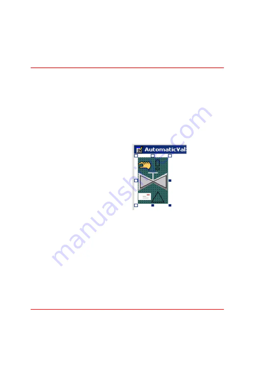
Select the PLC Subelements tab, and then create a Valve2Way element.
6.
Create an AlarmState, a WarningLevel and a ManIndication element by
double-clicking and place them next to the Valve Element.
7.
Add from the Library of Standard Symbols the OperatorMessage Icon and
place it in the lower left corner of the Valve Element. You need to set the
Stretch Property to True.
8.
Select the Valve Element. Via the Properties window, connect the
AnswerOpenedRef property to the process signal corresponding to whether
the valve is opened or not.
Connect the AnswerClosedRef property to the process signal corresponding to
whether the valve is closed or not. If desired, you need only connect one of the
process signals.
Figure 115. Creating a Valve Element
AlarmState
WarningLevel
OperatorMessage
ManIndicator
Содержание IndustrialIT Compact HMI 800
Страница 1: ...IndustrialIT Compact HMI 800 System Version 4 1 Getting Started ...
Страница 2: ......
Страница 3: ...IndustrialIT Compact HMI 800 System Version 4 1 Getting Started ...
Страница 18: ...Terminology About This Book 18 3BSE040587R4401 ...
Страница 20: ...System Overview Section 1 Compact HMI 800 Overview 20 3BSE040587R4401 ...
Страница 46: ...IP Addresses and Workgroups Section 3 Installation 46 3BSE040587R4401 ...
Страница 88: ...Import to Compact HMI 800 Section 4 Engineering 88 3BSE040587R4401 ...
Страница 111: ...Section 5 Operation Alarm and Event Usage 3BSE040587R4401 111 Figure 70 System Event List ...
Страница 112: ...Alarm and Event Usage Section 5 Operation 112 3BSE040587R4401 ...
Страница 188: ...Creating New Graphical Libraries Section 8 PLC Connect Graphic Elements 188 3BSE040587R4401 ...
Страница 191: ......


