Contents
4
FV4000 / FS4000
D184B097U02
4.11
Rotating the display......................................................................................................................................31
5
Electrical connections ...............................................................................................................................32
5.1
Cable connection area .................................................................................................................................33
5.1.1
HART design.........................................................................................................................................33
5.1.2
Fieldbus design .....................................................................................................................................35
5.2
Cable connection..........................................................................................................................................36
5.2.1
Standard design, HART ........................................................................................................................36
5.2.2
Connection via flameproof cable gland (“Ex d design“) ........................................................................36
5.2.3
Standard design, PROFIBUS PA / FOUNDATION Fieldbus ................................................................39
5.2.4
Remote mount design...........................................................................................................................41
5.3
M12 plug-in connector, PROFIBUS PA .......................................................................................................44
5.4
Switching output ...........................................................................................................................................45
5.5
Configuration of the switching output ...........................................................................................................46
5.6
Functional ground/Equipotential bonding.....................................................................................................48
6
Commissioning ..........................................................................................................................................49
6.1
Preliminary checks prior to start-up..............................................................................................................49
6.2
Commissioning the unit ................................................................................................................................49
6.2.1
Switching on the supply power .............................................................................................................49
6.2.2
Device configuration..............................................................................................................................49
6.3
Information on voltage/current consumption................................................................................................49
6.4
Setting the bus address (PROFIBUS PA)....................................................................................................50
6.5
Setting the bus address (FOUNDATION Fieldbus) .....................................................................................51
6.6
Checking the parameters .............................................................................................................................52
7
Communication ..........................................................................................................................................53
7.1
HART protocol communication.....................................................................................................................53
7.2
PROFIBUS PA communication....................................................................................................................55
7.3
FOUNDATION Fieldbus communication......................................................................................................58
7.4
Software history............................................................................................................................................61
7.4.1
TRIO-WIRL FV4000 HART version ......................................................................................................61
7.4.2
TRIO-WIRL FV4000 PROFIBUS PA ....................................................................................................61
7.4.3
TRIO-WIRL FV4000 FOUNDATION Fieldbus ......................................................................................61
8
Parameterization ........................................................................................................................................62
8.1
Standard display format ...............................................................................................................................62
8.2
Operation using the control buttons on the transmitter ................................................................................63
8.3
Navigation and data entry ............................................................................................................................65
8.3.1
Selecting parameters in a submenu .....................................................................................................65
8.3.2
Changing a parameter value.................................................................................................................65
8.3.3
Saving parameters ................................................................................................................................65
8.4
Parameter overview .....................................................................................................................................66
8.4.1
Menu levels ...........................................................................................................................................66
8.4.2
Menu level parameters..........................................................................................................................66
8.5
Programming protection ...............................................................................................................................67
8.5.1
Deactivating programming protection ...................................................................................................67
8.5.2
Activating programming protection .......................................................................................................68
8.6
Menu structure .............................................................................................................................................69
8.6.1
Menu structure – Enhancement for HART............................................................................................77
8.6.2
Menu structure – Enhancement for PROFIBUS PA .............................................................................79
8.6.3
Menu structure – Enhancement for FOUNDATION Fieldbus...............................................................82
Содержание FS4000
Страница 1: ...Operating Instruction D184B097U02 Vortex Flowmeter Swirl Flowmeter FV4000 FS4000 ...
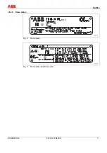
Страница 11: ...Safety D184B097U02 FV4000 FS4000 11 1 6 2 2 Name plates Fig 2 Name plate Fig 3 Name plate hazardous area ...
Страница 116: ...Appendix 116 FV4000 FS4000 D184B097U02 ...
Страница 117: ...Appendix D184B097U02 FV4000 FS4000 117 ...
Страница 118: ...Appendix 118 FV4000 FS4000 D184B097U02 ...
Страница 119: ...Appendix D184B097U02 FV4000 FS4000 119 ...
Страница 120: ...Appendix 120 FV4000 FS4000 D184B097U02 ...
Страница 125: ......


