ABB FPTC-02 Скачать руководство пользователя страница 84

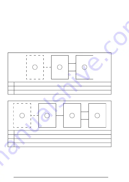
Safety block diagrams

The components that are included in the safety data calculations are
shown in the safety block diagrams below.

Note:

The failure rate of the PTC sensor is not included in the

calculations.

Two-channel configurations

This diagram is applicable to configuration 1.

1

2

3

PTC sensor

1

FPTC module

2

Drive STO

3

This diagram is applicable to configuration 2.

1

2

3

4

PTC sensor

1

FPTC module

2

FSO module

3

Drive STO

4

84 Technical data

Содержание FPTC-02

Страница 1: ... ABB INDUSTRIAL DRIVES FPTC 02 ATEX certified thermistor protection module Ex II 2 GD option L537 Q971 for ACS880 drives User s manual ...

Страница 2: ......

Страница 3: ...II 2 GD option L537 Q971 for ACS880 drives User s manual Table of contents 1 Safety instructions 5 Mechanical installation 6 Electrical installation 8 Start up and acceptance test 3AXD50000027782 Rev E EN EFFECTIVE 2020 02 28 2020 ABB Oy All Rights Reserved ...

Страница 4: ......

Страница 5: ...y 15 Compatibility 16 Target audience 16 Exclusion of liability 16 Related manuals 18 Terms and abbreviations 3 Hardware description 21 Contents of this chapter 21 Product overview 21 General 22 Operation basics 22 XFLT input Fault 22 XWRN input Warning 23 Layout 24 Markings 24 Module 24 Type designation label 25 ATEX markings 25 Drive 25 Option Q971 26 SMT function 4 Option description and instru...

Страница 6: ...nstallation 35 Contents of this chapter 35 Necessary tools and instructions 35 Unpacking and examining the delivery 36 Installing the module 6 Electrical installation 39 Contents of this chapter 39 Warnings 40 Necessary tools and instructions 40 General wiring instructions 41 Terminal designations 41 Wiring 43 Wiring example 1 44 Wiring example 2 45 Wiring example 3 46 Wiring example 4 47 Wiring e...

Страница 7: ...idation procedure 66 Acceptance test reports 67 Acceptance test 9 Fault tracing 71 Contents of this chapter 71 Reporting problems and failures related to safety functions 71 FPTC 02 module replacement 72 Fault and warning messages 74 LEDs 10 Maintenance 75 Contents of this chapter 75 Safety circuit maintenance 76 Proof test interval 77 Competence 77 Residual risk 77 Intentional misuse 77 Decommiss...

Страница 8: ...grams 84 Two channel configurations 85 One channel configurations 86 Response times 86 Relevant failure modes 87 Related standards and directives 88 Compliance with the European Machinery Directive 88 Compliance with the European ATEX Directive 91 ATEX certificate 94 TÜV Nord certificate Further information 8 Table of contents ...

Страница 9: ...otes Warnings tell you about conditions which can cause injury or death or damage to the equipment They also tell you how to prevent the danger Notes draw attention to a particular condition or fact or give information on a subject The manual uses these warning symbols WARNING Electricity warning tells about hazards from electricity which can cause injury or death or damage to the equipment Safety...

Страница 10: ... of Ex motors in Zone 1 21 equipment category 2 or Zone 2 22 equipment category 2 or 3 WARNING Obey the safety instructions of the drive If you ignore them injury or death or damage to the equipment can occur This manual does not contain the complete safety instructions of the drive It only includes the instructions related to the scope of this manual The general instructions are given in this sec...

Страница 11: ...ry circuits from the drive Do not do work on the drive motor cable or motor when they are energized Before you start the work do the steps in section Electrical safety precautions page 12 WARNING If a short circuit occurs in the output stage of the drive the STO function does not prevent the intermediate DC current from flowing through and heating up the motor The system integrator must take this ...

Страница 12: ...Open the disconnector of the supply transformer The main disconnecting device in the drive cabinet does not disconnect the voltage from the AC input power busbars of the drive cabinet Close the grounding switch or switches Q9 option F259 if present Do not use excessive force as the switch has electromagnetic interlocking If the drive is equipped with a DC DC converter unit optional Open the DC swi...

Страница 13: ...rking including but not limited to electric shock and arc protection Use a multimeter with an impedance greater than 1 Mohm Make sure that the voltage between the drive input power terminals L1 L2 L3 and the grounding PE busbar is close to 0 V Make sure that the voltage between the drive output terminals T1 U T2 V T3 W and the grounding PE busbar is close to 0 V Make sure that the voltage between ...

Страница 14: ...e is not equipped with a grounding switch install temporary grounding as required by the local regulations 7 Ask the person in control of the electrical installation work for a permit to work 14 Safety instructions ...

Страница 15: ...ure safety SMT function which uses the FPTC 02 module option L537 Q971 Compatibility The FPTC 02 module is compatible with ACS880 01 11 31 drives ACS880 04 04XT 04F 04FXT M04 14 34 drive modules ACS880 104 104LC inverter modules ACS880 07 17 37 and ACS880 17LC 37LC cabinet built single drives ACS880 107 107LC inverter units FSO 12 and FSO 21 safety functions modules Introduction to the manual 15 ...

Страница 16: ...ty of the system integrator or other party who is responsible for the overall system and system safety The system integrator or other responsible party must make sure that the entire implementation complies with the instructions in this manual all relevant standards directives and local electrical code and that the system is tested verified and validated correctly Related manuals Code Name Drive h...

Страница 17: ...C inverter units hardware manual Drive firmware 3AUA0000085967 ACS880 primary control program firmware manual PC tools 3AUA0000094606 Drive composer start up and maintenance PC tool user s manual Safety 3AUA0000048753 Functional safety Technical guide No 10 1SFC001008B0201 Safety and functional safety A general guide www abb com safety ABB Safety information and solutions 3AUA0000037223 Motors and...

Страница 18: ...lure EN ISO 13849 1 CCF Diagnostic coverage EN ISO 13849 1 DC Digital input DI Direct torque control a motor control method DTC Electromagnetic compatibility EMC An IEC term used in the context of explosive atmospheres IEC 60079 Ex Type of protection flameproof enclosures EN IEC 60079 1 Ex d Types of protection increased safety EN IEC 60079 7 Ex eb Ex ec Motors used in explosive atmospheres Ex mot...

Страница 19: ...EN IEC 61800 5 2 SMT Safe stop 1 IEC EN 61800 5 2 SS1 Safe stop emergency SSE Safe torque off IEC EN 61800 5 2 STO There are three categories of stop functions stop category 0 an uncontrolled stop where power to the machine actuators is removed immediately STO stop category 1 a controlled stop where the machine actuators have power for stopping after which the power is removed SS1 stop category 2 ...

Страница 20: ...ses the safety device must be replaced Note that any TM values given cannot be regarded as a guarantee or warranty EN ISO 13849 1 TM Potentially explosive atmosphere Hazardous areas are di vided into zones based on the frequency and duration of the occurrence of an explosive atmosphere EN IEC 60079 Zone 20 Introduction to the manual ...

Страница 21: ...s a protective device within the scope of the European ATEX Product Directive This allows the use of the module in temperature protection of motors in explosive atmospheres Ex motors Inside the module there is reinforced insulation between the motor thermistor connection and the other terminals of the module The insulation forms a reliable protective separation between the motor main circuit and t...

Страница 22: ...o the FPTC 02 module The FPTC 02 module then activates the SMT function by opening the drive Safe torque off STO circuit This activates the drive STO function The STO function disables the control voltage of the power semiconductors of the drive output stage This prevents the drive from generating the torque required to rotate the motor If the motor is running when the STO function is activated it...

Страница 23: ... Layout 1 1 2 4 3 XSTO2 XSTO1 XWRN XFLT Retaining clips 1 Lock 2 Hardware description 23 ...

Страница 24: ...Module Type designation label 3AXD50000017196A5450043WS ROHS ABB OY FPTC 02 SN A5450043WS CODE 3AXD50000017196 1 2 3 4 5 Type 1 Serial number in format RYWWSSSSWS where 2 R Component revision Y Last digit of the manufacturing year for example 5 2015 WW Manufacturing week for example 01 week 1 SSSS Number that starts every week from 0001 WS Manufacturing location ABB MRP code of the module 3 Combin...

Страница 25: ...led outside the potentially explosive atmosphere 3 Certified for use in explosive atmospheres caused by 4 G gases vapors or mists D dust Drive Option Q971 When the FPTC 02 module is ordered as a factory installed option an additional sticker is sometimes attached to the drive module to signify ATEX classification of the drive Safe disconnection function Q971 of the drive module This sticker and th...

Страница 26: ... potentially explosive atmosphere 4 Certified for use in explosive atmospheres caused by 5 G gases vapors or mists D dust Certificate reference 6 The option code Q971 is included in the type designation label of the drive In cabinet built drives this is on the cabinet door In cabinet built drives there is no separate ATEX classification label for the Safe disconnection function SMT function When t...

Страница 27: ...oduct Directive 2014 34 EU 1 Notified Body Eurofins Expert Services Formerly VTT Expert Services now part of the Eurofins Group Specific marking of explosion protection 2 Equipment group II Product for surface industry other than mining ap plications 3 Equipment category 2 Parentheses show that the drive or inverter unit must be installed outside the potentially explosive atmosphere 4 Certified fo...

Страница 28: ...28 ...

Страница 29: ...function you can connect the FPTC 02 module directly to the drive Safe torque off STO circuit or you can use it together with an FSO module The FSO safety functions module FSO 12 or FSO 21 is an optional device used with the ACS880 drives to implement safety functions When installed it reserves the standard STO connection of the drive Safety functions in the FSO module can open the drive STO circu...

Страница 30: ...the option module to an option slot of the drive control unit and sets the applicable drive parameters connects the PTC temperature sensors of the motor to the PTC inputs of the option module connects the drive STO terminals to the STO output of the option module or to the FSO module and then configures the FSO module to do the STO function Cabinet built drives For cabinet built ACS880 single driv...

Страница 31: ...des also the ATEX certified Safe torque off function STO Commissioning the drive for a motor in a hazardous area Commission the drive according to the requirements and limitations set by the application the motor manufacturer s instructions drive firmware manual local laws and regulations and this manual The certificate of the Ex motor typically requires that you set a minimum limit for the output...

Страница 32: ...utside the permitted safe temperature range XFLT input The WARNING LED is red when motor temperature is outside the temperature warning range XWRN input 2 Safe motor temperature fault XFLT or motor temperature warning XWRN in the drive 3 STO indication in the drive The drive STO indication is active when the SMT safety function has activated the drive STO function The type of the indication is set...

Страница 33: ...ore information see the hardware and firmware manuals of the drive inverter module FSO module The fault reaction function of the FSO module trips the drive if it detects a failure The FSO module activates the STO or Safe stop emergency SSE function This activates the drive STO function The drive STO function is active until the fault is repaired Note With the FPTC module the recommended type of th...

Страница 34: ...et the FSO module switch the power off and on or press the Boot FSO button on the Safety view of Drive composer pro or set drive parameter 96 09 FSO reboot For more information see the drive firmware manual and the FSO module user s manual 34 Option description and instructions ...

Страница 35: ...Torx screwdriver T10 For a complete list of tools see the applicable drive hardware manual Unpacking and examining the delivery 1 Open the option package 2 Make sure that the package contains FPTC 02 module STO cable ATEX label with the ATEX classification markings this manual 3 Make sure that there are no signs of damage to any of the items Mechanical installation 35 ...

Страница 36: ...ning clips lock it into position 4 Push in the lock 5 Tighten the screw The maximum tightening torque is 0 8 N m 7 1 lbf in Note The screw tightens the connections and grounds the module It is necessary for fulfilling the EMC requirements and for correct operation of the module WARNING Tightening the screw too much can cause damage to the threads See the applicable drive manual for further instruc...

Страница 37: ...2 3 1 4 Mechanical installation 37 ...

Страница 38: ...38 ...

Страница 39: ...or damage to the equipment can occur If you are not a qualified electrical professional do not do installation or maintenance work WARNING Cabinet built drives Do not connect test or measure a drive based on the diagrams in this manual Each delivery is unique Before starting the work on the electric circuits of a drive always refer to the delivery specific circuit diagrams Electrical installation ...

Страница 40: ...x Zone must comply with the requirements for the applicable type of protection such as Ex d EN IEC 60079 1 Ex eb EN IEC 60079 7 Ex e in EN 60079 7 2007 and IEC 60079 7 2006 Ex ec EN IEC 60079 7 Ex nA in EN IEC 60079 15 2010 3 Install the drive or inverter unit including the components of the ATEX certified motor thermal protection function outside the potentially explosive atmosphere 4 For the sen...

Страница 41: ...TO terminals Wiring example 1 page 43 The STO outputs of the FPTC 02 module are connected directly to the STO terminals of the drive ACS880 drives and modules In the factory installed option L537 Q971 the wiring is done at the factory according to this example ACS880 cabinet built drives In the option L537 Q971 terminal block X969 is located between the module and the drive control board not shown...

Страница 42: ...he drive with a one channel connection Wiring example 5 page 47 The STO outputs of the FPTC 02 module are connected to an FSO module and the STO outputs of the FSO module to the STO terminals of the drive with a one channel connection If you use a one channel connection make sure that you can reach the required safety integrity level SIL If you do not use the XFLT input Fault connect a resistor 10...

Страница 43: ...ND IN1 IN2 SLOT 1 2 3 X100 XSTO2 3 Ex M a 1 2 Control unit 1 Potentially explosive atmosphere 2 a If necessary you can connect an external device for example an emergency stop button between the XSTO input of the control unit and the XSTO1 and XSTO2 outputs of the FPTC module See Wiring example 3 page 45 Electrical installation 43 ...

Страница 44: ...IL2 capable redundancy between STO channels 11 12 21 22 XSTO1 PTC XSTO T1 T2 XFLT FPTC OUT SGND IN1 IN2 SLOT 1 2 3 X100 XSTO2 X114 FSO 10 9 8 7 6 5 4 3 2 1 10 9 8 7 6 5 4 3 2 1 X113 X111 1 2 3 4 1 3 Ex M 2 Control unit 1 Potentially explosive atmosphere 2 44 Electrical installation ...

Страница 45: ...ection This connection is SIL2 capable redundancy between STO channels 11 12 21 22 XSTO1 PTC XSTO T1 T2 XFLT FPTC OUT SGND IN1 IN2 SLOT 1 2 3 X100 XSTO2 1 2 3 Ex M 3 Control unit 1 External safety relay 2 Potentially explosive atmosphere 3 Electrical installation 45 ...

Страница 46: ... XSTO1 PTC XSTO T1 T2 XFLT FPTC OUT SGND IN1 IN2 SLOT 1 2 3 X100 XSTO2 3 Ex M a 1 2 Control unit 1 Potentially explosive atmosphere 2 a If necessary you can connect an external device eg an emergency stop button between the XSTO input of the control unit and the XSTO2 output of the FPTC module 46 Electrical installation ...

Страница 47: ...1 capable no redundancy between STO channels 11 12 21 22 XSTO1 PTC XSTO T1 T2 XFLT FPTC OUT SGND IN1 IN2 SLOT 1 2 3 X100 XSTO2 X114 FSO 10 9 8 7 6 5 4 3 2 1 10 9 8 7 6 5 4 3 2 1 X113 X111 1 2 3 4 3 Ex M 1 2 Control unit 1 Potentially explosive atmosphere 2 Electrical installation 47 ...

Страница 48: ...48 ...

Страница 49: ...odule parameter settings Drive inverter Use the Drive composer PC tool or the control panel to set the parameter values This table lists the parameters related to the safety function in ACS880 primary control program For more information see the drive firmware manual Parameter settings 49 ...

Страница 50: ... stopped when this occurs STO indication run stop 31 22 For more information see the firmware manual The drive generates a warning both when the drive is running and when it is stopped Warning Warning This parameter value does not have an ef fect on the SMT function but this is the re commended setting For the cabinet built drives ABB has set this value at the fact ory 50 Parameter settings ...

Страница 51: ... 0 No default Warnings from the module in slot 1 not suppressed Disable slot 1 warning 1 1 Yes Warnings from the module in slot 1 suppressed 1 Yes Module installed in slot 2 Module in slot 2 2 0 No default Warnings from the module in slot 2 not suppressed Disable slot 2 warning 3 1 Yes Warnings from the module in slot 2 suppressed 1 Yes Module installed in slot 3 Module in slot 3 4 0 No default Wa...

Страница 52: ...e warning Warning active in slot 2 5 1 Yes An FPTC module has been detec ted in slot 3 Module found in slot 3 6 1 Yes The module in slot 3 has an active SMT fault Fault active in slot 3 7 1 Yes The module in slot 3 has an active motor temperature warning Warning active in slot 3 8 Reserved 9 15 Contains hardware related settings that can be enabled and disabled by toggling the specific bits Specia...

Страница 53: ...rameters 35 50 35 55 motor cable protection parameters 35 60 35 62 For more information see the drive firmware manual FSO module If you use an FSO module option Q972 or Q973 in the safety system configuration set the parameters according to the system requirements Example values are shown in this section You need the Drive composer pro PC tool to set the FSO module parameters You also need a passw...

Страница 54: ... the drive STO circuit immediately after the safety function request from the FPTC module stop category 0 With the FPTC module you cannot use a stop function with a deceleration ramp stop category 1 The FPTC module always generates a fault and activates the drive STO function immediately in overtemperature situations Note Setting parameters related to STO and SS1 can also have an effect on other s...

Страница 55: ...thod of the FSO module Automatic Power up ac knowledge ment FSO GEN 41 Automatic You do not need to push a reset button after switching on the FSO module The FSO module generates the acknowledgement signal automat ically after the power up Manual The FSO module reads the external acknowledgement signal through the digital input defined by parameter FSOGEN 42 Make sure that the value is Automatic S...

Страница 56: ...are related to the STO function of the FSO module With stop category 0 the FSO module activates the STO function in overtemperature situations Also the FSO module can activate the STO function in fault situations Description Example value Name Index Sets the acknowledgement method used in the STO SSE and SS1 func tions Automatic STO acknow ledgement STO 02 Automatic The FSO module resets the STO f...

Страница 57: ...en the FSO module has activ ated the STO function and opened the drive STO circuit With this parameter you can let the drive restart before the motor has stopped fly start This parameter is applicable only if the STO function is requested from STO input A STO 11 or STO input B STO 12 2000 ms Restart delay after STO STO 13 STO function Adjust the value when necessary If you do not want to use the f...

Страница 58: ...nsafe after this time acknowledgement is allowed For example if the drive modulation is lost during SLS deceleration ramp SLS OK will be indicated after this time has elapsed STO function This parameter sets the time after which the STO function is completed and the STO completed in dication goes on Parameter STO 13 defines the time after which the acknow ledgement is allowed Adjust the value acco...

Страница 59: ...easures to ensure sufficient diagnostic coverage of the wiring failures Parameters for the SSE function These parameters are related to the Safe stop emergency SSE function of the FSO module The safety functions described in this manual do not use this function but the FSO module can activate the SSE function in internal fault situations Description Example value Name Index Sets the type of the SS...

Страница 60: ...hese parameters only when you use a safety pulse encoder and the FSE 31 pulse encoder interface module with the FSO 21 module Description Example value Name Index Activates the FSE 31 encoder interface and shows the version of the encoder parameter groups 91 and 92 Version 1 FSE 3X act and par version 200 231 Shows the number of safety pulse en coders connected to the FSE module Single en coder CH...

Страница 61: ...s too small will cause an encoder fault A7D8 A value that is too big will prevent the encoder dia gnostic related to this parameter Sets the rotation direction for the safety pulse encoder 1 Gear numerat or encoder 1 S_ENC GEN 41 With this parameter you can change the rotation direction of the motor Ad just the default value if necessary Sets the type of the safety pulse en coder interface module ...

Страница 62: ... revolution of the safety pulse encoder parameter 92 10 Notes ACS880 07 17 37 and ACS880 17LC 37LC drives with option Q978 In motor overtemperature situations the FSO module also opens the main contactor circuit breaker ACS880 07 17 37 and ACS880 17LC 37LC drives with option Q978 or Q979 The FSO module is configured so that after the safety function activation the user must reset the FSO module ma...

Страница 63: ...he temperature too much In some cases you cannot use the brake for the motor deceleration when the motor thermal protection circuit has tripped and the motor temperature is too high For more information see the drive firmware manual or the FSO module user s manual if you use the Safe brake control SBC function of the FSO module Parameter settings 63 ...

Страница 64: ...64 ...

Страница 65: ...e test validation to validate the correct operation of safety functions Competence The acceptance test of the safety function must be carried out by a competent person with expertise and knowledge of the safety function as well as functional safety as required by IEC 61508 1 clause 6 and ATEX Ex regulations The test procedures and report must be documented and signed by this person Start up and ac...

Страница 66: ...s in the logbook of the machine and in the explosion protection document under the scope of the ATEX User Directive 1999 92 EC The report must include as required by the referred standards a description of the safety application including a figure a description and revisions of safety components that are used in the safety application a list of all safety functions that are used in the safety appl...

Страница 67: ...mal protection function corresponds to the Ex classification of the environment and the Ex motor The motor manufacturer selects the PTC sensors for the motor temper ature measurement according to the specified temperature class Make sure that the temperature on off resistances match those of the module If you have done any changes to the wiring do a check of the connec tions against the applicable...

Страница 68: ...the STO is activated and that the motor coasts to a stop Make sure that you cannot start the drive before you have reset the drive Reset the drive Make sure you cannot reset and restart the drive before the input resistance in the XFLT input decreases to less than 1 6 kohm Restart the drive and the motor Make sure that they operate normally Cause a short circuit situation Decrease the resistance i...

Страница 69: ...r resistance 100 ohm 1 kohm between the XWRN inputs Make sure that the motor temperature warning indication is activated in motor overtemper ature and short circuit situations Fill in and sign the acceptance test report which verifies that the safety function is safe and accepted to operation Start up and acceptance test 69 ...

Страница 70: ...70 ...

Страница 71: ...ault and warning messages of the drive and LEDs on the module Reporting problems and failures related to safety functions Contact ABB FPTC 02 module replacement If there is a failure in the FPTC 02 module you have to replace it with a new one You cannot repair the module Fault tracing 71 ...

Страница 72: ...he motor is not overloaded 4 Make sure that the drive parameter settings are correct 5 Examine the wiring of the temperature sensor If necessary repair the wiring 6 Measure the resistance of the sensor If necessary replace the sensor The FPTC 02 module in option slot 1 indicates overtemperature in the XFLT input safety related 1 Motor temperature is too high or 2 the thermistor is short circuited ...

Страница 73: ... option slot 1 has activated a motor temperature warning in the XWRN input non safety related 1 Motor temperature is too high or 2 the thermistor is short circuited or disconnected Motor temperature 1 1 A497 The FPTC module in option slot 2 has activated a motor temperature warning in the XWRN input non safety related See A497 Motor temperature 2 1 A498 The FPTC module in option slot 3 has activat...

Страница 74: ... The motor temperature is outside the temperature warning range or there is no PTC sensor connected to the XWRN input non safety related Red WARNING The module is powered up Green STATUS Note When there is no sensor connected to the XWRN input the WARNING LED is red even if you have suppressed the warnings from the module You can connect a resistor 100 ohm 1 kohm 1 4 W wire wound in the XWRN input...

Страница 75: ...fetime It is a good practice to check the operation of the safety function when other maintenance routines are carried out on the machinery Include this check in the routine maintenance program of the machinery that the drive runs If you change any wiring or component after the start up replace the FPTC 02 module modify parameters or restore parameters to their factory default values Use only ABB ...

Страница 76: ... design of the complete safety function should also note the Recommendation of Use CNB M 11 050 published by the European co ordination of Notified Bodies concerning dual channel safety related systems with electromechanical outputs When the safety integrity requirement for the safety function is SIL 3 or PL e cat 3 or 4 the proof test for the function must be performed at least every month When t...

Страница 77: ...educe the recognized hazardous conditions In spite of this it is not always possible to eliminate all potential hazards Therefore the warnings for the residual risks must be given to the operators Intentional misuse The safety circuit is not designed to protect a machine against intentional misuse Decommissioning When you decommission the module make sure that the safety of the machine is maintain...

Страница 78: ...78 ...

Страница 79: ...tains the technical data of the module gives general rules notes and definitions related to safety functions and lists the related standards and directives The safety data relevant certificates and Declarations of Conformity are also included Technical data 79 ...

Страница 80: ...NFORMATION CONFIDENTIAL 3AXD50000017196 ASSEM B 0 Based on Prepared J Diov 24 Jun 15 Title ASSEMBLY DRAWING Doc des Customer Check 24 Jun 15 ASSEMBLY D Appr 24 Jun 15 Resp dept Cust Doc No Project name Doc No DMS Number Weight kg 0 24 A Initial Approval 24 Jun 15 J Diov Isolation areas The following figure shows the different isolation areas of the module Isolation areas A and B and the mounting s...

Страница 81: ...is 2 PTC Warning 3 PTC Fault 4 STO 1 5 STO 2 6 There is reinforced insulation between isolation areas A and C isolation areas B and C Connections Motor thermistor connection Maximum wire size 2 5 mm2 14 AWG Maximum wire length 700 m 2300 ft 1400 m 4600 ft for the whole loop Technical data 81 ...

Страница 82: ...mm2 16 AWG with FSO module Maximum wire length 30 m 98 ft for the whole loop Tightening torque 0 5 N m 4 4 lbf in Contact rating 24 V DC 17 30 V 1 A channel Maximum breaking capacity 1000 VA Ambient conditions For the environmental limits for the safety functions and the drive refer to the hardware manual of your drive Safety data The FPTC 02 module is a type A safety component as defined in IEC 6...

Страница 83: ...e drive STO FSO module with STO function request one channel configuration See Wiring example 5 page 47 One channel configurations Two channel configurations 5 4 3 2 1 Configuration 1 1 2 2 2 SIL SILCL c c c c c PL 60 60 90 90 90 SFF 8 25E 09 7 68E 09 5 48E 09 5 54E 09 5 48E 09 PFH 1 h T1 20 a 6 71E 05 6 17E 05 4 81E 05 4 88E 05 4 81E 05 PFDavg T1 2 a 1 69E 04 1 56E 04 1 20E 04 1 21E 04 1 20E 04 P...

Страница 84: ...s below Note The failure rate of the PTC sensor is not included in the calculations Two channel configurations This diagram is applicable to configuration 1 1 2 3 PTC sensor 1 FPTC module 2 Drive STO 3 This diagram is applicable to configuration 2 1 2 3 4 PTC sensor 1 FPTC module 2 FSO module 3 Drive STO 4 84 Technical data ...

Страница 85: ...PTC module 2 External safety relay 3 Drive STO 4 Note The failure rate of the external safety relay is not included in the calculation One channel configurations This diagram is applicable to configuration 4 1 2 3 PTC sensor 1 FPTC module 2 Drive STO 3 Technical data 85 ...

Страница 86: ...s Relevant failure modes The SMT function activates when not necessary safe failure The SMT function does not activate when requested A fault exclusion on the failure mode short circuit on printed circuit board has been made EN 13849 2 table D 5 The analysis is based on the assumption that one failure occurs at one time No accumulated failures have been analyzed The failures of the PTC sensor ther...

Страница 87: ...y of machinery Safety related parts of control sys tems Part 1 General principles for design EN ISO 13849 1 2015 Safety of machinery Safety related parts of control sys tems Part 2 Validation EN ISO 13849 2 2012 Safety of machinery Electrical equipment of machines Part 1 General requirements EN 60204 1 2018 IEC 60204 1 2016 Electrical equipment for measurement control and labor atory use EMC requi...

Страница 88: ...s a safety component This function complies with European harmonized standards such as EN IEC 61800 5 2 The declarations of conformity are shown below Compliance with the European ATEX Directive The safety function of this manual option L537 Q971 is within the scope of the ATEX product directive 2014 34 EU as a protective system The function complies with European harmonized standard EN 50495 The ...

Страница 89: ...Technical data 89 ...

Страница 90: ...90 Technical data ...

Страница 91: ...ATEX certificate ATEX certificate for the Safe motor temperature function with the FPTC 02 module and ACS880 drive series VTT 15 ATEX 050 Technical data 91 ...

Страница 92: ...92 Technical data ...

Страница 93: ...Check the latest version of the certificate in the ABB Library Technical data 93 ...

Страница 94: ...TÜV Nord certificate TÜV Nord certificate for the FPTC 02 module and ACS880 drive series is attached below 94 Technical data ...

Страница 95: ... by navigating to www abb com searchchannels Product training For information on ABB product training navigate to new abb com service training Providing feedback on ABB manuals Your comments on our manuals are welcome Navigate to new abb com drives manuals feedback form Document library on the Internet You can find manuals and other product documents in PDF format on the Internet at www abb com dr...

Страница 96: ...www abb com drives 3AXD50000027782E 2020 ABB Oy All Rights Reserved Specifications subject to change without notice 3AXD50000027782 Rev E EN EFFECTIVE 2020 02 28 ...

Отзывы: