


3
2. Forced ventilation
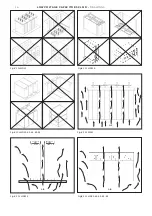
Forced cooling using a fan is sometimes required (Fig.
#6). Please refer to the following recommendations:
• Consider the maximum ambient temperature of the
installation site including the heating effect of the
capacitor installation itself.
• Consider the heat dissipated from all the compo-
nents and apparatus in the cubicle: reactors, capaci-
tors, contactors, fuses, etc.
• Consider the maximum permissible temperatures for
all the components and apparatus.
• Consider how to direct the airflow with respect to
the position of the capacitors (Fig. #6).
3. The use of an overtemperature protection is recom-
mended in order to switch the bank off in case of fan
failure or overtemperature due to other cause.
4. Regular maintenance and cleaning of any filters is
necessary. Without regular cleaning the cooling system
may become inefficient.
CLMD13 group assembly
To make a group of several CLMD13 capacitor units (up
to 4 maximum):
1. CLMD13 units are delivered with top protection cov-
ers already mounted. Unscrew them before assem-
bling.
2. Place the CLMD13 capacitor units on a plane and firm
punched surface (or support bars), side by side. Please
note the CLMD13 orientation is highlighted by top “U”
marking next to its power terminals as well as an arrow
print on the top cover. U and arrow markings must
match. Make sure all CLMD13 of a group have the same
orientation(Fig. #7).
3. Align them together by their black terminal plates
(Fig. #8).
4. Install interconnection bars (optional) between re-
spective terminals and fix them with the delivered
bolts with a torque of 3Nm (recommended torque for
M6 according to DIN 46-200) (Fig. #9).
5. For proper IP protection degree, open the necessary
knock-outs in the top covers for interconnection bars
and put them back over the capacitor units.
CLMD fixation (Fig. #10)
Fix each CLMD unit through its fixation slots with ap-
propriate screws/bolts (not included).
For CLMD33 /33S, at least 4 fixation holes must be
used. Make sure that the rigidity of the support and the
screws are sufficient to bear the weight of the CLMD
capacitor unit(s).
Electrical connection
Power supply
Cables should be rated at minimum 1.5 times the nomi-
nal capacitor current.
Appropriate cable shoes (cable lugs for CLMD33 /33S
type) must be used in accordance with good common
practice of electrical installation.
While tightening the bolt, a torque of
3Nm
Ò
M6
6Nm
Ò
M8
10Nm
Ò
M10
15Nm
Ò
M12
(recommended torque according to DIN46-200)
should be applied for proper electrical connection,
without damaging the cable (not applicable for
CLMD33 / 33S type). Ensure that all connections are
tight and cables pass through the dedicated knock out
and appropriate grommet.
WARNING!
the power cables must be connected at the
side of the terminals without discharge resistor (as
shown (Fig. #11); connections at the side with dis-
charge resistor might damage the cable due to resis-
tors surface temperature.
Earthing
CLMD43-45, 53-63-65, 83-85 fit a M8 terminal under
the protection cover for earthing connection. Use ap-
propriate cable shoes and apply a 6Nm torque for tight
connection. For other CLMD types, earthing is
achieved through fixation points of the enclosure.
Harmonics
Installation of capacitors on networks disturbed by
harmonics may require special precautions especially
when there is a risk of resonance phenomena.
Commissioning
With the equipment isolated from the supply, check:
• Cabling is properly connected ;
• Ambient ventilation is adequate;
• Correct tightness of the connections.
Accessories
(Optional and for CLMD13 only)
Interconnection bars
The interconnection bars allow making one group of
CLMD13 capacitor units connected in parallel. One kit
of three bars is needed for a group of two CLMD13 ca-
pacitor units.
For installation revert to CLMD13 group assembly para-
graph.
Maintenance
1. Ensure safety procedures are completed (see para-
graph “Safety”);
2. Yearly maintenance should include:
• Removal of dust deposits, cleaning of all parts;
• Check of tightness of all electrical connections;
• Check of ambient temperature;
• Check condition of discharge resistors.
While every care is taken to ensure that the information con-
tained in this publication is correct, no legal responsibility
can be accepted for any inaccuracy. We do not accept respon-
sibility for any misuse of the product. The company reserves
the right to alter or modify the information contained herein
at any time in the light of technical or other developments.
en


