2
3
Drive STO status
SSE status
B
C
1
A
Motor speed
Time
D
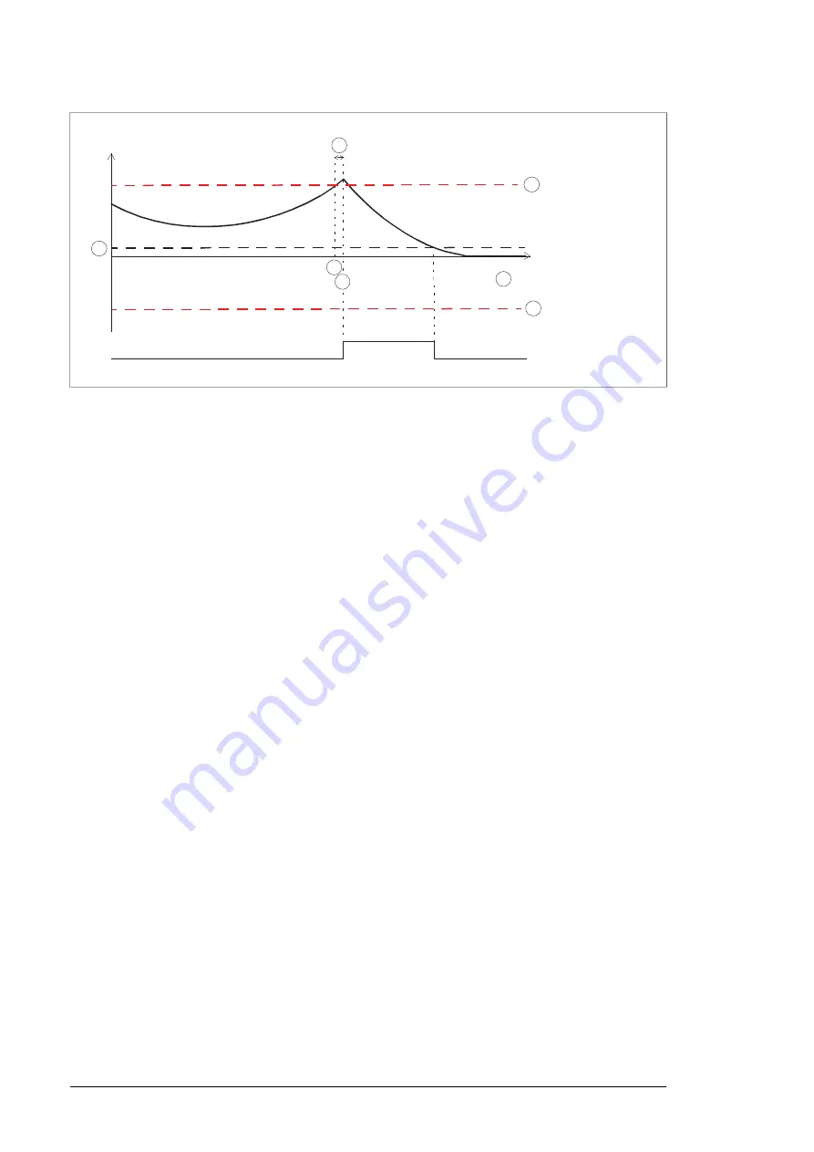
Safety function response time
A
SMS trip limit positive (parameter SMS.14)
B
SMS trip limit negative (parameter SMS.13)
C
Zero speed with encoder (parameter FSOGEN.52)
D
1.
The motor speed reaches the SMS trip limit positive.
2.
After the safety function response time (A), the FSO module activates the SSE function
which in turn activates the drive STO function. The motor coasts to a stop. In this case,
the SSE function is configured as “Immediate STO” (parameter SSE.13).
Note:
In the +Q978 option, the SBC function is used to control the main
contactor/breaker. If you have this option in the drive, the main contactor/breaker is
opened if the SMS trip limit is reached.
3.
When the motor speed reaches the zero speed limit (D), the FSO module acknowledges
the SSE function (in this case automatic acknowledgement is used and no external
acknowledgement input is in use, see parameter STO.02) and deactivates the drive
STO function. The user must reset the drive if the STO indication parameter (FSOGEN.62
or 31.22) has been set so that a fault is generated. See chapter General parameters.
■
SSM function
When the motor speed is between the SSM limits, the SSM indication signal in the FSO
module is on.
There are four separate SSM functions in the FSO module with different parameter settings.
The SSM1 function is used as an example and in the delivered default settings of the +Q965
option. ABB activates the SSM1 function at the factory. The user sets the SSM positive and
negative SSM speed limits at the start-up. For more information, see section Parameter
settings and FSO module user’s manual.
This time scheme diagram illustrates the operation of the SSM1 function.
28 Option description


