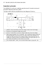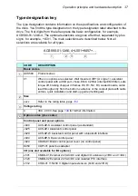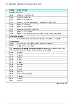
30 Operation principle and hardware description
Frames R6…R9
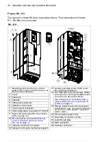
The layout of a frame R6 drive is presented below. The constructions of frames
R7…R9 differ to some extent.
1
Mounting points (2 at the top, 2 at the
bottom of the main part of the frame, 2 at
the top of the cable box)
2
Cover
3
Cable box
4
Heatsink
5
Lifting holes (6 pieces)
6
Assistant control panel
7
Control panel connection
8
Cold configuration connection for CCA-01
9
Power OK and Fault LEDs. See section
on page
.
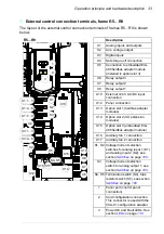
10 I/O connections. See section
control connection terminals, frame
11 Cable tie mounts for I/O cables
12 Clamps for I/O cable mechanical support
13 Varistor grounding screw (VAR), under
the control panel platform
14 Two EMC filter grounding screws (EMC),
one under the control panel platform and
one at the left, above the shroud.
See
Checking the compatibility with IT
(ungrounded) and corner-grounded TN
on page
.
15 Shroud. Under the shroud: Input power
connection (L1, L2, L3), motor connection
(T1/U, T2/V, T3/W) and DC connection
(UDC+, UDC-).
16 PE connection (power line)
17 Grounding connection (motor)
18 Lead-through plate
19 Main cooling fan
20 Auxiliary cooling fan
R6…R9
1
5
2
4
3
5
6
7
8
9
10
9
13
14
20
18
15
12
12
16
11
1
19
14
5
PE
17
Содержание ACS580-01 drives
Страница 1: ...ABB general purpose drives Hardware manual ACS580 01 drives 0 75 to 250 kW...
Страница 4: ......
Страница 11: ...Table of contents 11 Document library on the Internet 225...
Страница 12: ...12 Table of contents...
Страница 36: ...36 Operation principle and hardware description Locations of the labels on the drive 1 2 3 1 2 3...
Страница 72: ...72 Planning the electrical installation...
Страница 79: ...Electrical installation 79 R6 R9 3 3 4...
Страница 108: ...108 Electrical installation 0 5 0 6 N m 0 5 0 6 N m 10 4 3 R5 4 6 8 7 4 8 9 5 11 11 0 4 lbf ft 0 4 lbf ft...
Страница 109: ...Electrical installation 109 R6 R9 0 5 0 6 N m 0 4 lbf ft 0 5 0 6 N m 0 4 lbf ft M4 20 4 6 10 3 4 4 5 7 8 9 8 11 11...
Страница 123: ...Maintenance and hardware diagnostics 123 3 Install the fan assembly in reverse order 2b R0 R1 R2 2b R3 2b R4 2b...
Страница 132: ...132 Maintenance and hardware diagnostics...
Страница 168: ...168 Dimension drawings Frame R0 IP21 3AXD10000257110...
Страница 169: ...Dimension drawings 169 Frame R0 IP55 3AXD10000341562...
Страница 170: ...170 Dimension drawings Frame R1 IP21 3AXD10000257188...
Страница 171: ...Dimension drawings 171 Frame R1 IP55 3AXD10000336766...
Страница 172: ...172 Dimension drawings Frame R2 IP21 3AXD10000257203...
Страница 173: ...Dimension drawings 173 Frame R2 IP55 3AXD10000341578...
Страница 174: ...174 Dimension drawings Frame R3 IP21 3AXD10000257219...
Страница 175: ...Dimension drawings 175 Frame R3 IP55 3AXD10000335424...
Страница 176: ...176 Dimension drawings Frame R4 IP21 3AXD10000332430...
Страница 177: ...Dimension drawings 177 Frame R4 IP55 3AXD10000427933...
Страница 178: ...178 Dimension drawings Frame R5 IP21 3AXD10000412280...
Страница 179: ...Dimension drawings 179 Frame R5 IP55 3AXD10000415964...
Страница 180: ...180 Dimension drawings Frame R6 IP21 3AXD10000258705...
Страница 181: ...Dimension drawings 181 Frame R6 IP55 3AXD10000330667...
Страница 182: ...182 Dimension drawings Frame R7 IP21 3AXD10000258995...
Страница 183: ...Dimension drawings 183 Frame R7 IP55 3AXD10000330932...
Страница 184: ...184 Dimension drawings Frame R8 IP21 3AXD10000287670...
Страница 185: ...Dimension drawings 185 Frame R8 IP55 3AXD10000332446...
Страница 186: ...186 Dimension drawings Frame R9 IP21 3AXD10000287428...
Страница 187: ...Dimension drawings 187 Frame R9 IP55 3AXD10000334310...
Страница 188: ...188 Dimension drawings...
Страница 196: ...196 Resistor braking...
Страница 226: ...Contact us AXD50000018826 Rev D EN 2015 11 02 www abb com drives www abb com drivespartners 3AXD50000018826D...

