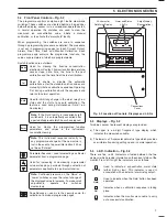


5
L
N
N/C
C
N/O
N/C
C
N/O
N/C
C
N/O
N/C
C
N/O
N/C
C
N/O
+
-
+
-
RELAY
1
RELAY
2
CAL
OUT
OF
SERVICE
OUT
OF
SAMPLE
O/P 1
O/P 2
MAINS
INPUT
STD1
STD2
HEATER
230V
Mains Voltage Selector
110V to120V
220V to 240V
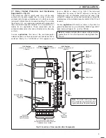
User
Cable
Entry
Glands
External
User
Connection
Terminals
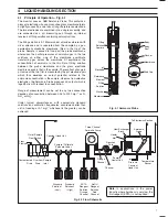
Interconnection Cable from/to
Microprocessor Unit and Instrument
Components (wet section)
Internal
Interconnection
Cable Terminals
Solenoid Valves
and Heater
Indicators
Relay
Board
Mains
Transformer
Mains Fuse –
1A, 250V AC (T)
Cable Gland
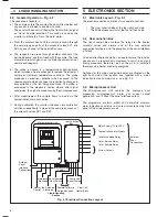
MAINS
MAINS
F1 250V
1A
PUMP
Mains 'ON'
Indicator
Mains
ON / OFF
Switch
Pump
ON / OFF
Switch
OFF
ON
OFF
ON
230V Position
220V min. to 240V max. AC
50/60Hz
115V Position
110V min. to 120V max. AC
50/60Hz
0.5A (T)
5A (F)
F3
F2
2
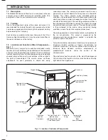
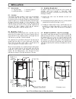
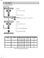
INSTALLATION…
Fig. 2.3 Location of User Junction Box Components
Note
. The mains and pump ON/
OFF switches are situated on the
right hand side of the junction box.
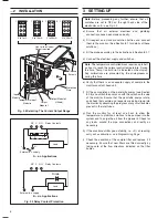
2.7
Relay Contact Protection and Interference
Suppression – Fig. 2.5
If the relays are used to switch loads on or off the relay
contacts can become eroded due to arcing. Arcing also
produces radio frequency interference (r.f.i.) which can cause
instrument malfunctions and incorrect readings. To minimize
the effects of r.f.i., arc suppression components are required;
these are resistor/capacitor networks for a.c. applications, or
diodes for d.c. applications. These components can be
connected either across the load or directly across the relay
contacts.
For
a.c. applications
the value of the resistor/capacitor
network depends on the load current and inductance that is
switched. Initially fit a 100 R/0.022
μ
F RC suppressor unit
(part no. B9303) as shown in Fig. 2.5A. If the instrument
malfunctions the value of the RC network is too low for
suppression and an alternative value must be used. If the
correct RC suppressor unit cannot be obtained, contact the
manufacturer of the switched device for details of the RC unit
required.
For
d.c. applications
fit a diode as shown in Fig. 2.5B. For
general applications use an alternative IN5406 type (600 V
peak inverse voltage at 3 A – part no. B7363).
Note.
For reliable switching the minimum voltage must be
greater than 12 V and the minimum current greater than
100 mA.


