


9
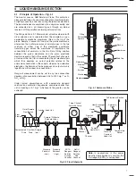
5-digit Display
(Concentration)
Alarms
Hold
Cal
Fail
1
2
Hold
Cal
Enter
Mode
20-character
Dot-Matrix Display
Alarm and Status
L.E.D.s
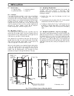
Connections
Cover
5
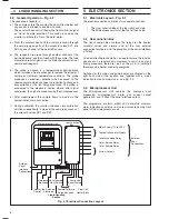
ELECTRONICS SECTION
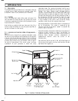
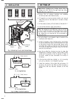
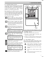
Fig. 5.2 Location of Controls, Displays and L.E.D.s
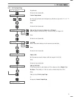
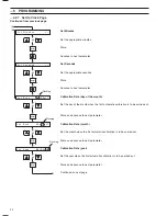
5.4
Front Panel Controls – Fig. 5.2
The programme controls comprise eight tactile membrane
switches. These switches are situated behind a hinged door
below the display, access is via a screwdriver-operated catch.
In normal operation the switches are used to view the
measured ion concentration value, initiate a manual
calibration, or to activate the 'alarm hold' facility.
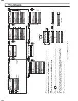
When programming, the switches are used to sequence
through a programming procedure as detailed. The procedure
is set out in programming pages for Input, Current Output,
Alarms, Real Time Clock and Monitor Calibration. Each
programme page contains the programme functions, the
values or parameters of which are programmable.
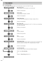
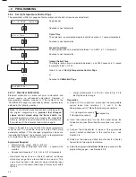
Switch functions are as follows:
Mode
Used for viewing the fluoride concentration,
electrode mV output, flowcell control temperature,
sensor slope, date, time, the time to the next
calibration and the time from the last calibration.
Cal
Used to enable or disable the automatic
calibrations, enter the standard solution values and
manually initiate a calibration sequence. Operating
'Cal' during a calibration aborts the sequence and
returns to normal operation.
Hold
Used to inhibit any change in the alarm relay/l.e.d.
status and the start of any auto calibration. The
feature is used during maintenance ('Hold' l.e.d.
illuminated).
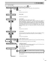
Note.
If the 'Hold' facility is inadvertently left
switched-in, it is automatically cancelled after
a period of approximately 3 hours has elapsed.
Enter
Used for storing the programmed function
parameters and values in the instrument's
nonvolatile memory.
Note.
The instrument responds instantly to
any programme change but the new value is
lost in the event of a power interruption if it has
not been 'Entered'.
Parameter Advance – used for selecting a particular
parameter from a programme page.
Used for increasing or decreasing a parameter
value or stepping up or down through a selection of
parameters applicable to a particular function.
Note.
Continued pressure on the 'Raise' or
'Lower' switches causes the rate of change of
the displayed value to increase. To make small
adjustments, operate the switches
momentarily.
Page Advance – used, via the security code, for
selection of individual programme pages.
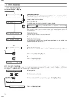
5.5
Displays – Fig. 5.2
Two blue vacuum fluorescent displays are provided:
a) The upper is a 5-digit 7-segment type display which
indicates the measured variable.
b) The lower is a 20-character dot matrix type which provides
user information during setting up and in normal operation.
5.6
L.E.D. Indication – Fig. 5.2
There are five l.e.d's (indicators situated between the two
displays) which provide information on the current status of the
monitor. From left to right the indicators are as follows:
A1
or
A2
Used to indicate a concentration alarm state
(either high or low). This indicator is used in
association with an external alarm relay output.
Hold
Used to indicate when the 'Hold' button has been
operated.
Cal
Indicates when a calibration sequence is taking
place.
Fail
Indicates when the monitor was unable to carry
out a successful calibration.


