


3
Junction
Box
60 Top of Case
30
Sample Inlet
& Drain
Tubes
110mm minimum clearance
required for access to locks
Fixing Centres
Moulded Case
Shown in
Open Position
780
Fixing
Centres
278
482
220
Cable
Entry
Point
188
890
Open
Position
95
°
Max.
angle of
opening
542
235
550
Closed
Position
8mm Keyhole
Slot
8mm Fixing
Holes
Top View
Edge of
Case
All dimensions in mm
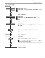
2
INSTALLATION
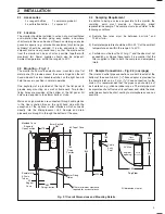
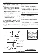
Fig. 2.1 Overall Dimensions and Mounting Details
2.1
Accessories
2 x reagent bottles
1 x ammonia probe kit
4 x calibration bottles
1 x spares kit
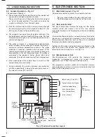
2.2
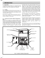
Location
The monitor should be installed in a clean, dry, well ventilated
and vibration-free location giving easy access, and where
short sample lines can be used. Rooms containing corrosive
gases or vapours (e.g., chlorination equipment or chlorine gas
cylinders) should be avoided. It is also advisable to have
adjacent drains near ground level, so that the waste outlet
from the monitor can be as short as possible, together with
maximum fall. Power supplies should also be adjacent.
Ambient temperature: within the range 5 to 40
°
C.
2.3
Mounting – Fig. 2.1
The monitor has a moulded plastic case, mounted onto a flat
metal panel. To provide access, the case is hinged on the left
hand side and has two lockable catches on the right hand to
hold the case in position in normal operation.
One keyhole slot is provided at the top of the flat panel to
provide easy mounting on a wall or framework. Two further
fixing holes are provided at the bottom of the flat panel. All
holes are designed to take 8 mm bolts or studs.
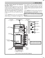
Mains and signal cables are connected through cable glands
in the User Junction Box on the right hand side with the
exception of the optional serial interface which connects
directly into the Microprocessor Unit. Sample and drain
pipework are brought in through the bottom of the case.
2.4
Sampling Requirement
In addition to being as close as possible to the monitor, the
sampling point must provide a thoroughly mixed
representative sample. The sample must also conform to the
following conditions:
a) Sample flow rates must be between 5 ml min
–1
and
1250 ml min
–1
.
b) Sample temperature should be within 20
°
C of the ambient
temperature and within the range 0 to 40
°
C.
c) Particles must be less than 10 mg l
–1
and the size must not
exceed 60
μ
m. Above these levels it is essential that the
filter supplied is fitted in both the sample and emergency
inlets.
2.5
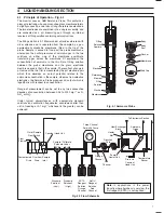
Sample Connections – Fig. 2.2 (overpage)
The inlet and outlet pipe connections are both located at the
bottom of the case. A 6 mm (
1
/
4
") hose adaptor is provided for
the sample inlet and a 9 mm (
3
/
8
") hose connection for the
drains. It is recommended that the pipes used should be of
inert material, e.g., silicone rubber or p.v.c. The inlet pipe must
incorporate a shut-off valve at its upstream end, while the drain
outlet pipes should be short, venting to atmosphere as soon as
possible.


