


8
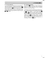
Flow Cell
Heater Block
Heater
Control
Microprocessor Unit
User Junction
Box
Mains Supply 115 to 230 V
Concentration Alarm Relays
Calibration Mode Relay
Out of Service Relay
Current Outputs
Out of Sample Relay
External
User
Connections
External
Serial
Interface
Connections
Reference
Electrode
Ion-Selective
Electrode
Sample/Calibrate
Soleniod Valves
Interconnection
Cables
Out of Sample
Float Switch
Pump and
Stirrer Motors
Liquid Handling
Section
…4
LIQUID HANDLING SECTION
5
ELECTRONICS SECTION
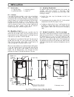
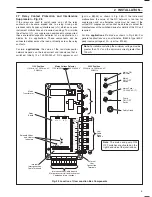
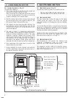
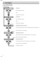
Fig. 5.1 Electrical Connections Layout
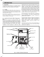
4.2
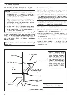
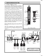
General Operation – Fig. 4.2
The sequence of events is:
a) The sample enters the constant head unit from below and
any excess is allowed to overflow to drain.
The constant head unit is fitted with a float switch to signal
an 'Out of Sample' condition. This switch is used by the
monitor to initiate the 'Out of Sample' alarm.
b) From the constant head unit the sample is drawn through
the normally open ports of the solenoid valves SV1 and
SV2 by one channel of the peristaltic pump.
c) The reagents are drawn through another channel of the
peristaltic pump, and then mixed with the sample. The tube
diameters are arranged so as to obtain the correct ratio of
sample and reagents.
d) The probe is housed in a temperature controlled block
which includes a heat exchanger to remove the effects of
sample and ambient temperature variations. The probe
produces an electrical potential when exposed to the
reacted sample which changes in proportion to changes in
concentration of the ion being measured. The probe is
connected to the electronic section where, after digital
conversion, the signal is processed by the microprocessor.
e) After measurement the sample flows to waste via the
contaminated drain connection.
f)
During calibration the monitor introduces two calibration
solutions sequentially in place of the sample by means of
the solenoid valves SV1 and SV2.
5.1
Electronic Layout – Fig. 5.1
The electronic section comprises two separate sections:
•
The User Junction Box at the top right hand side.
•
The Microprocessor Unit at the top left hand side.
5.2
User Junction Box
The User Junction Box contains the relays for the heater,
solenoid valves and alarms, and all the user external
connection terminals, with the exception of the serial interface
(if fitted).
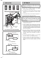
Once installed there should be no need to remove the junction
box cover on a regular basis. However, to assist in any fault
finding procedure, there are l.e.d's on the p.c.b. to indicate if
the relays and heater are being energised.
Switches for the mains and pump/heater are situated on the
right hand side of the junction box, together with a mains
indication lamp and mains fuse – see Fig. 2.3.
5.3
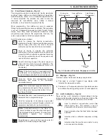
Microprocessor Unit
The Microprocessor Unit contains the analogue input
processing, microprocessor, alarm and current output
generation, and (if fitted) the serial interface output.
The programme controls, digital and dot-matrix displays,
alarm indication and status l.e.d's are all mounted on the front
panel of the microprocessor unit.


