35
2 6 6 H S H MODBUS TR A N S M IT TE R |
P R E SSU R E/ T EM P ER AT U R E M U LT I VA R I A B L E | O I/ 2 6 6 H SH M T- EN R E V. A
For additional information, refer to the operating
instructions included with the handheld terminal.
If the transmitter has been configured in the factory
according to customer specifications for the measuring
point, all you have to do is mount the transmitter as
prescribed (to correct potential zero shifts, refer to the
section “Correcting the zero shift”), and switch it on. The
measuring point will now be ready for use.
If, however, you wish to make changes to the
configuration, a handheld terminal or - preferably - a
graphical user interface (DTM) is required. This DTM tool
renders the device fully configurable. It supports both the
HART protocol and PROFIBUS PA fieldbus protocol, and
can be run on a PC or laptop, or as part of an automation
system. Where FOUNDATION Fieldbus is concerned, the
device description (DD), which can be loaded onto various
configuration tools, is required for configuration
purposes.
Refer to the installation manual provided with the
software for the steps required to install the operating
tool. The most important parameters can be set via the
path “Parametrize_Differential Pressure Measurement”.
The program offers the option of configuring, polling, and
testing the transmitter.
In addition, offline configuration can be performed by
means of an internal database.
Each configuration step is subject to a plausibility check.
You can call up context-sensitive help at any time by
pressing the “F1” key. Immediately after you have received
the transmitter or before you change the configuration,
we recommend that you save the existing configuration
data to a separate data storage medium, via the path
“File_Save”.
7.13 Configuration with the graphical user
interface (DTM) - System requirements
— Operating control program (e.g., ABB Asset Vision
Basic version 1.00.17 or higher)
— DTM (Device Type Manager; graphical user interface)
— Operating system (depending on the respective
control program)
To operate the Asset Vision Basic please refer to the
relevant operating instruction.
7.14 Standard and Advanced HART: functionality
266 Pressure Transmitters can be codified with:
— Advanced HART and 4 to 20 mA
— Standard HART and 4 to 20 mA
— HART and 4 to 20 mA Safety, certified to IEC 61508
Advanced and Standard HART feature some differencies in
terms of functionality.
Functionality
266 Advanced HART 266 Standard HART
Configuration via HMI
On board
Not available
SIL certified
On board
Not available
PILD
On board
On board
Trend
On board
Not available
Totalizer
On board
On board
Service Port
On board
Not available
Electronic replacement
On board
Not available
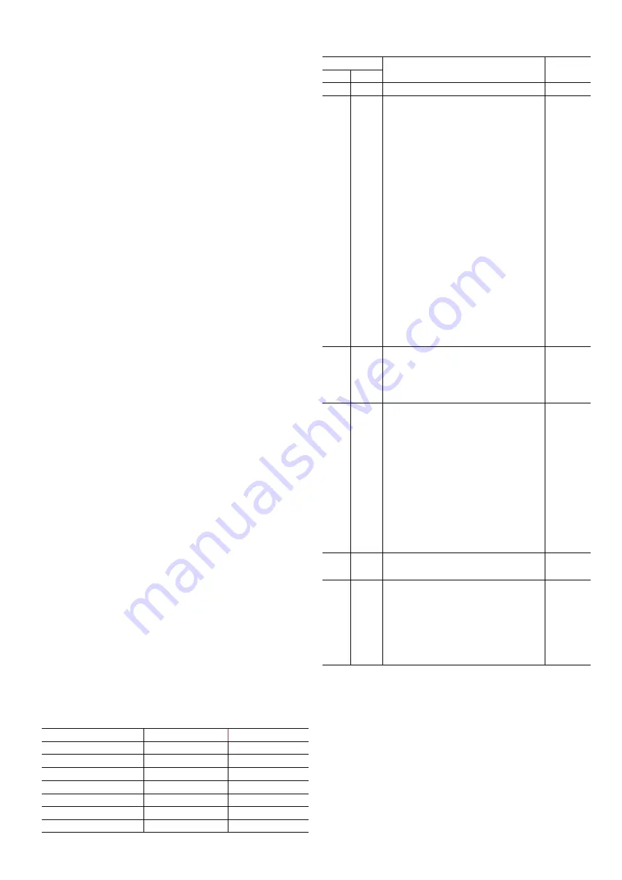
7.15 Advanced HART software revision history
Revision
Description
Release
date
From To
7.1.11
First release
09/2009
7.1.11
7.1.12
Bug Fixing:
— microbar and millitor units added
— HART command 35 bug fixed. By HART
specificaiton #35 unit should not be
set pv unit
— if the local indicator was not mounted,
only one operation via push buttons
was performed
— MWP diagnosis classification become
Maintenance instead of
Off-Specification
Improvements:
— replacement functionality improved
— internal improvements to reduce
factory configuration
— more/stronger checks about process
variables goodness
— HART response time reduced (30%)
06/2010
7.1.12 7.1.14
Improvements:
— factory configuration speeded up
— service detailed diagnosis
implemented
01/2011
7.1.14 7.1.15
Bug Fixing:
— sensor trimming via local display was
performend only in kPa
— diagnosis “Replace Error” no more
shown
— unit strings on display (Nm3, bbl, t)
were wrong
New Features:
— new language (French & Spanish) on
local indicator
— sensor polarity invertion
01/2013
7.1.15 7.2.1
HART 7 implementation
11/2015
7.1.15
7.2.1
7.1.16
(HART 5)
7.2.2
(HART 7)
New Features:
— Temperature alarm enabled by user
— oscillation alarm control
— switching of alarm for wrong power
supply
10/2018
7.15
7.16


