


P. 78 - Chap. 11 Spare Parts and Service Centres
G
B
11
Spare Parts and
Service Centres
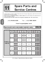
The Manufacturer provides an effi cient after-sales service through a large service network and a Technical
Department for solving any problems.
Always specify the
compressor model
and
serial number
when communicating with Authorized Service
Centres and the Manufacturer.
To locate the service Centre closest to the compressor installation site, call or send a fax to:
(+
44
)
01
869
-
326226
Fax:
(+
44
)
01
869
-
326216
E-mail: s
upport
@abac.
co.uk
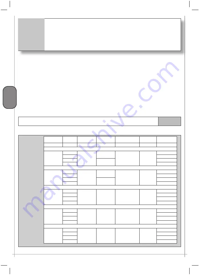
Spare parts and consumable material codes
11.1
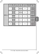
The following tables show the most commonly used spare parts. Contact an authorised service Centre for
other spare parts.
Model
Pressure
Air
fi lter
Oil
fi lter
Separator fi lter
Suction
prefi lter
Transmission
belts
bar
Code
Code
Code
Code
Code
5.5
8
9056293
9056238
9056237
9623572
(2) 9075257
10
(2) 9075290
13
9056282
(2) 9075236
15
(2) 9075290
7.5
8
9056293
9056238
9056237
9623572
(2) 9075256
10
(2) 9075236
13
9056282
(2) 9075290
15
(2) 9075257
11
8
9056293
9056113
9056292
9623572
(2) 9075291
10
(2) 9075215
13
(2) 9075254
15
(2) 9075256
15
BA 51
8
9056293
9056113
9056292
9623572
(3) 9075211
10
(3) 9075291
13
(3) 9075215
15
(3) 9075262
15
BA 69
8
9618034
9056113
9056292
9623572
(3) 9075256
10
(3) 9075254
13
(3) 9075262
15
(3) 9075215
FORMULA
GENESIS
Содержание FORMULA Series
Страница 1: ...GENESIS FORMULA MODULO 5 5 15 kW USE AND MAINTENANCE HANDBOOK GB ...
Страница 2: ......
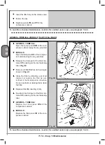
Страница 11: ...IX FORMULA 15 kW BA 69 Fig 17 Fig 18 PC PE SPA CF FA PF CT TRL VR BF PS ES EV FU MA RA RO MP PP VA FO FO VS SS ...
Страница 12: ...X MODULO 5 5 7 5 kW Fig 19 Fig 20 FO FD FA SS ES FU MA RA RO PP MP PC PE SCE SF VA EV BF VT TRL CT PF VS PS ...
Страница 14: ...XII MODULO 15 kW BA 69 Fig 23 Fig 24 PS PP PF MA FU RA RO ES VA FO FD VS SS MP CF FA SCE PE PC TRL VR BF CT EV ...
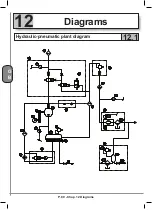
Страница 82: ...P 80 Chap 12 Diagrams G B 12 Diagrams Hydraulic pneumatic plant diagram 12 1 ...
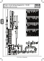
Страница 84: ...P 82 Chap 12 Diagrams G B Power circuit wiring diagram 5 5 15 kW Machines without air dryer 12 2 ...
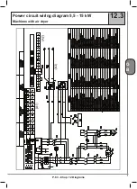
Страница 85: ...P 83 Chap 12 Diagrams G B Power circuit wiring diagram 5 5 15 kW Machines with air dryer 12 3 ...
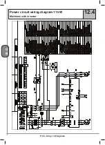
Страница 86: ...P 84 Chap 12 Diagrams G B Power circuit wiring diagram 11 kW Machines with inverter 12 4 ...
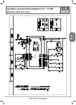
Страница 87: ...P 85 Chap 12 Diagrams G B Auxiliary circuit wiring diagram 5 5 15 kW Machines without air dryer 12 5 ...
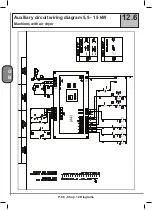
Страница 88: ...P 86 Chap 12 Diagrams G B Auxiliary circuit wiring diagram 5 5 15 kW Machines with air dryer 12 6 ...
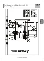
Страница 89: ...P 87 Chap 12 Diagrams G B Auxiliary circuit wiring diagram 11 kW Machines with inverter 12 7 ...
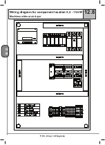
Страница 90: ...P 88 Chap 12 Diagrams G B Wiring diagram for component location 5 5 15 kW Machines without air dryer 12 8 ...
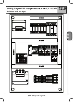
Страница 91: ...P 89 Chap 12 Diagrams G B Wiring diagram for component location 5 5 15 kW Machines with air dryer 12 9 ...


