


P. 39 - Chap. 7 Start-up and operation
G
B
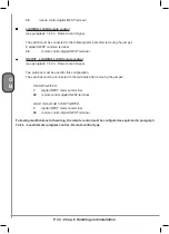
If LINE 3 shows “Ready for start”, the compressor can be started.
The compressor is started by pressing the
green K1-START key
At this point, the compressor may:
a)
start
, displaying the messages referring to the start and functioning phases
b)
prepare to start with the following message
In this case, network pressure is above the minimum
threshold value set; the compressor will start automatically
in the case of a request for air from the network
3
Stand by auto start
hour-date
c)
prepare to start with the following message
In this case, the remote control function has been enabled
(see paragraph 7.4.2.3).
The compressor will start when the remote command is
received
4
Stand by rem. com.
hour-date
d)
prepare to start with the following message
In this case, the daily or weekly programming function
has been enabled and the compressor is in the OFF
programming phase (see paragraph 7.4.2.6).
The compressor will start when an
ON programming
phase is initiated
.
5
Stand by progr. com.
hour-date
If the compressor does not start or none of the cases listed above occurs, refer to chapter 9.
The following contacts will be made in sequence:
LINE - STAR - DELTA
6
Start
hour-date
Start
hour-date
and one of the two messages will be displayed
7
Unload run
hour-date
Load run
hour-date
When the display shows “
Load run
” the intake valve is open and the machine operates at full load (produces
the nominal capacity of compressed air).
During functioning, delivery pressure increases; once the preset maximum line pressure threshold value has
been reached, the control system sets the compressor to idling by closing the intake valve (“
Unload run
”).
When the pressure drops below the preset minimum threshold value, the intake valve opens again and the
machine restarts functioning at full load.
During
unload run
, two cases may arise:
a)
Setting of
AUTOMATIC
functioning
(see paragraph 7.4.2.3):
Содержание FORMULA Series
Страница 1: ...GENESIS FORMULA MODULO 5 5 15 kW USE AND MAINTENANCE HANDBOOK GB ...
Страница 2: ......
Страница 11: ...IX FORMULA 15 kW BA 69 Fig 17 Fig 18 PC PE SPA CF FA PF CT TRL VR BF PS ES EV FU MA RA RO MP PP VA FO FO VS SS ...
Страница 12: ...X MODULO 5 5 7 5 kW Fig 19 Fig 20 FO FD FA SS ES FU MA RA RO PP MP PC PE SCE SF VA EV BF VT TRL CT PF VS PS ...
Страница 14: ...XII MODULO 15 kW BA 69 Fig 23 Fig 24 PS PP PF MA FU RA RO ES VA FO FD VS SS MP CF FA SCE PE PC TRL VR BF CT EV ...
Страница 82: ...P 80 Chap 12 Diagrams G B 12 Diagrams Hydraulic pneumatic plant diagram 12 1 ...
Страница 84: ...P 82 Chap 12 Diagrams G B Power circuit wiring diagram 5 5 15 kW Machines without air dryer 12 2 ...
Страница 85: ...P 83 Chap 12 Diagrams G B Power circuit wiring diagram 5 5 15 kW Machines with air dryer 12 3 ...
Страница 86: ...P 84 Chap 12 Diagrams G B Power circuit wiring diagram 11 kW Machines with inverter 12 4 ...
Страница 87: ...P 85 Chap 12 Diagrams G B Auxiliary circuit wiring diagram 5 5 15 kW Machines without air dryer 12 5 ...
Страница 88: ...P 86 Chap 12 Diagrams G B Auxiliary circuit wiring diagram 5 5 15 kW Machines with air dryer 12 6 ...
Страница 89: ...P 87 Chap 12 Diagrams G B Auxiliary circuit wiring diagram 11 kW Machines with inverter 12 7 ...
Страница 90: ...P 88 Chap 12 Diagrams G B Wiring diagram for component location 5 5 15 kW Machines without air dryer 12 8 ...
Страница 91: ...P 89 Chap 12 Diagrams G B Wiring diagram for component location 5 5 15 kW Machines with air dryer 12 9 ...


