


P. 30 - Chap. 6 Handling and installation
6
Handling and
installation
G
B
6.1
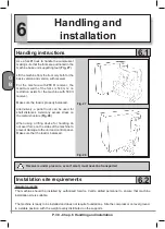
Handling instructions
Use a forklift truck to handle the compressor
making sure that the forks are positioned in the
machine base unit supporting feet (
Fig. 27
).
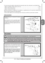
Lift the machine from the front only both for the
basic version and version with receiver.
For the machine with
270 lt
receiver, the
maximum width of the forks is 540 mm; no
restriction exists for the machine with 500 lt
receiver.
Make sure the load is properly balanced.
Alternatively, a pallet truck can be used for
short distances. Avoid any excess stress on
the metal structure (
Fig. 28
).
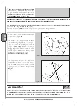
When using a lifting device for handling do
not exert force on the sides of the machine to
prevent damage to the unit and control panel.
Make sure that the load is balanced.
Fig. 27
Fig. 28
Receivers under pressure, even if small, must never be transported
6.2
Installation site requirements
General remarks
The machine should be installed by authorised Service Centre skilled personnel to ensure that machine
installation site is suitable.
The machine is ready to be installed and does not require foundations. Site the compressor on level ground,
in a stable position, with the weight evenly distributed on the supports.
Содержание FORMULA Series
Страница 1: ...GENESIS FORMULA MODULO 5 5 15 kW USE AND MAINTENANCE HANDBOOK GB ...
Страница 2: ......
Страница 11: ...IX FORMULA 15 kW BA 69 Fig 17 Fig 18 PC PE SPA CF FA PF CT TRL VR BF PS ES EV FU MA RA RO MP PP VA FO FO VS SS ...
Страница 12: ...X MODULO 5 5 7 5 kW Fig 19 Fig 20 FO FD FA SS ES FU MA RA RO PP MP PC PE SCE SF VA EV BF VT TRL CT PF VS PS ...
Страница 14: ...XII MODULO 15 kW BA 69 Fig 23 Fig 24 PS PP PF MA FU RA RO ES VA FO FD VS SS MP CF FA SCE PE PC TRL VR BF CT EV ...
Страница 82: ...P 80 Chap 12 Diagrams G B 12 Diagrams Hydraulic pneumatic plant diagram 12 1 ...
Страница 84: ...P 82 Chap 12 Diagrams G B Power circuit wiring diagram 5 5 15 kW Machines without air dryer 12 2 ...
Страница 85: ...P 83 Chap 12 Diagrams G B Power circuit wiring diagram 5 5 15 kW Machines with air dryer 12 3 ...
Страница 86: ...P 84 Chap 12 Diagrams G B Power circuit wiring diagram 11 kW Machines with inverter 12 4 ...
Страница 87: ...P 85 Chap 12 Diagrams G B Auxiliary circuit wiring diagram 5 5 15 kW Machines without air dryer 12 5 ...
Страница 88: ...P 86 Chap 12 Diagrams G B Auxiliary circuit wiring diagram 5 5 15 kW Machines with air dryer 12 6 ...
Страница 89: ...P 87 Chap 12 Diagrams G B Auxiliary circuit wiring diagram 11 kW Machines with inverter 12 7 ...
Страница 90: ...P 88 Chap 12 Diagrams G B Wiring diagram for component location 5 5 15 kW Machines without air dryer 12 8 ...
Страница 91: ...P 89 Chap 12 Diagrams G B Wiring diagram for component location 5 5 15 kW Machines with air dryer 12 9 ...


