


P. 77 - Chap. 10 Maintenance
G
B
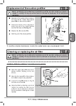
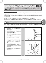
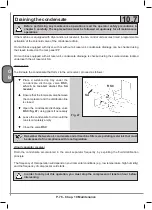
Remove the front panel
PF
with the key
provided
Connect fitting
R
provided, which must
communicate with a suitable collection
recipient, to fitting
DO
after unscrewing
the safety plug (
Fig. 48
)
Partially open drain valve
RSO
(
Fig.
48
)
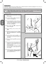
Follow the operation and close oil drain
valve RSO as soon as oil starts flowing
out
Check the oil level and top up, if
required, as described in the paragraph
“
Checking the level and topping up
”
Replace the safety plug and the PF
panel
Fig. 48
SA
RSC
DO
RSO
The air receiver and separator condensate should be drained manually on a weekly basis - or more
frequently. The user is responsible for this maintenance operation.
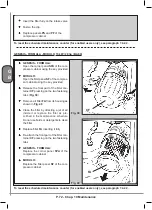
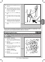
Replacing the fuses
10.8
Before performing any maintenance operations read the operator safety precautions in
chapter 5 carefully. These precautions must be followed scrupulously for all maintenance
operations
GENESIS - FORMULA:
Open the corner panel
SPA
of the com-
pressor cabinet using the key provided
MODULO:
Open the electric box panel
SCE
using
the key provided
Replace the damaged fuses. Follow
the amperage specifications provided
in paragraphs 12.8, 12.9
GENESIS - FORMULA:
Close the corner panel
SPA
MODULO:
Close the electric box panel
SCE
Fig. 49
R
Содержание FORMULA Series
Страница 1: ...GENESIS FORMULA MODULO 5 5 15 kW USE AND MAINTENANCE HANDBOOK GB ...
Страница 2: ......
Страница 11: ...IX FORMULA 15 kW BA 69 Fig 17 Fig 18 PC PE SPA CF FA PF CT TRL VR BF PS ES EV FU MA RA RO MP PP VA FO FO VS SS ...
Страница 12: ...X MODULO 5 5 7 5 kW Fig 19 Fig 20 FO FD FA SS ES FU MA RA RO PP MP PC PE SCE SF VA EV BF VT TRL CT PF VS PS ...
Страница 14: ...XII MODULO 15 kW BA 69 Fig 23 Fig 24 PS PP PF MA FU RA RO ES VA FO FD VS SS MP CF FA SCE PE PC TRL VR BF CT EV ...
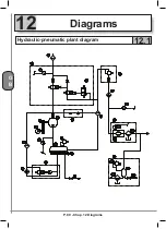
Страница 82: ...P 80 Chap 12 Diagrams G B 12 Diagrams Hydraulic pneumatic plant diagram 12 1 ...
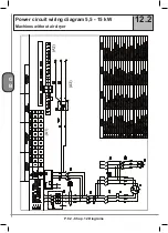
Страница 84: ...P 82 Chap 12 Diagrams G B Power circuit wiring diagram 5 5 15 kW Machines without air dryer 12 2 ...
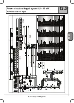
Страница 85: ...P 83 Chap 12 Diagrams G B Power circuit wiring diagram 5 5 15 kW Machines with air dryer 12 3 ...
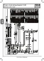
Страница 86: ...P 84 Chap 12 Diagrams G B Power circuit wiring diagram 11 kW Machines with inverter 12 4 ...
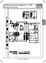
Страница 87: ...P 85 Chap 12 Diagrams G B Auxiliary circuit wiring diagram 5 5 15 kW Machines without air dryer 12 5 ...
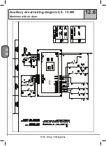
Страница 88: ...P 86 Chap 12 Diagrams G B Auxiliary circuit wiring diagram 5 5 15 kW Machines with air dryer 12 6 ...
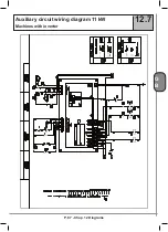
Страница 89: ...P 87 Chap 12 Diagrams G B Auxiliary circuit wiring diagram 11 kW Machines with inverter 12 7 ...
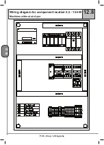
Страница 90: ...P 88 Chap 12 Diagrams G B Wiring diagram for component location 5 5 15 kW Machines without air dryer 12 8 ...
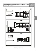
Страница 91: ...P 89 Chap 12 Diagrams G B Wiring diagram for component location 5 5 15 kW Machines with air dryer 12 9 ...


