


P. 27 - Chap. 4 Performance and specifications
G
B
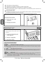
4.7
Lubricated and cooling fluid
The compressor is filled with
DICREA 46
lubricated and cooling fluid
Total capacity:
7 Kg
Top up with lubricated and cooling fluid with the
same specifications as the
lubricated and cooling fluid
in
the machine (synthetic coolant I.E. ABAC DURALUBE may be specified)
Contact the Manufacturer’s technical Department before using
lubricated and cooling fluids
with other
specifications
4.8
Dryer
Thermostat controlled cooling cycle, direct expansion, with Freon R134a gas; pressure dew point
temperature 3°C, clean air filtering degree 0,01mm.
Filtration degree: 1
µ
m.
Oil carryover:
0,1 mg/m
3
Displayable dew point temperature
Cooling compressor and timed condensate drain, controlled from mc panel
2
4.9
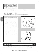
Clearance requirements and system layouts
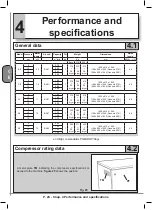
The tables with the overall dimensions of the compressor are provided in
figures 1-12
The hydraulic/pneumatic system diagram and the wiring diagrams (operation and location) are shown in
Chapter 12
Содержание FORMULA Series
Страница 1: ...GENESIS FORMULA MODULO 5 5 15 kW USE AND MAINTENANCE HANDBOOK GB ...
Страница 2: ......
Страница 11: ...IX FORMULA 15 kW BA 69 Fig 17 Fig 18 PC PE SPA CF FA PF CT TRL VR BF PS ES EV FU MA RA RO MP PP VA FO FO VS SS ...
Страница 12: ...X MODULO 5 5 7 5 kW Fig 19 Fig 20 FO FD FA SS ES FU MA RA RO PP MP PC PE SCE SF VA EV BF VT TRL CT PF VS PS ...
Страница 14: ...XII MODULO 15 kW BA 69 Fig 23 Fig 24 PS PP PF MA FU RA RO ES VA FO FD VS SS MP CF FA SCE PE PC TRL VR BF CT EV ...
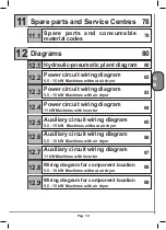
Страница 82: ...P 80 Chap 12 Diagrams G B 12 Diagrams Hydraulic pneumatic plant diagram 12 1 ...
Страница 84: ...P 82 Chap 12 Diagrams G B Power circuit wiring diagram 5 5 15 kW Machines without air dryer 12 2 ...
Страница 85: ...P 83 Chap 12 Diagrams G B Power circuit wiring diagram 5 5 15 kW Machines with air dryer 12 3 ...
Страница 86: ...P 84 Chap 12 Diagrams G B Power circuit wiring diagram 11 kW Machines with inverter 12 4 ...
Страница 87: ...P 85 Chap 12 Diagrams G B Auxiliary circuit wiring diagram 5 5 15 kW Machines without air dryer 12 5 ...
Страница 88: ...P 86 Chap 12 Diagrams G B Auxiliary circuit wiring diagram 5 5 15 kW Machines with air dryer 12 6 ...
Страница 89: ...P 87 Chap 12 Diagrams G B Auxiliary circuit wiring diagram 11 kW Machines with inverter 12 7 ...
Страница 90: ...P 88 Chap 12 Diagrams G B Wiring diagram for component location 5 5 15 kW Machines without air dryer 12 8 ...
Страница 91: ...P 89 Chap 12 Diagrams G B Wiring diagram for component location 5 5 15 kW Machines with air dryer 12 9 ...


