
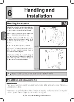


P. 38 - Chap. 7 Start-up and operation
G
B
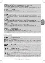
Display
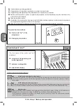
DI
DI Multi-function display
Back-lit LCD display with four lines of twenty characters each: shows compressor operating conditions and is used
to carry out all programming and control operations
7.2.2
Emergency stop button
Fig.36
The red EMERGENCY STOP button PE (
ref.
figure 36
) stops the machine immediately.
Use this button for emergencies only
in conditions which appear hazardous
for the operator or for the machine
(see
“
Compressor emergency STOP
” below).
7.3
Starting and stopping the compressor
STARTING the compressor
When the machine is switched on (powered) the control unit starts the
initial sequence
and prepares to control the
compressor.
According to the sequence, with the
LP led ON steadily
, the following screen page must be shown on display DI:
This screen page indicates:
LINE 1
name of the compresso
LINE 2
/
LINE 3
software version which may differ from that
indicated
LINE 4
serial number of control unit, different for each
machine
1
<<<<mc
2
>>>>
Ve r s . S o f t . : 1 . 0 . 0 . 1
S/N: 000-00-01-00001
After a few seconds, the display shows the main screen page:
This screen page indicates:
LINE 1
indication of network pressure
LINE 2
indication of compression temperature of air-
oil mixture
LINE 3
messages about operating conditions
LINE 4
hour and date, informations menu access,
tree menu access, quick language change
message
2
Pressione XX.X bar
Temperatura XXX °C
Pronto all’avvio
10:40 DOM 25/05/2003
To change the language, use the
K5
and
K6
keys
If the compressor is operating, LINE 1 and LINE 2 always show the above information.
Particular indications (error messages), additional information or the information of the management
menu are displayed on LINE 3 and on LINE 4.
Содержание FORMULA Series
Страница 1: ...GENESIS FORMULA MODULO 5 5 15 kW USE AND MAINTENANCE HANDBOOK GB ...
Страница 2: ......
Страница 11: ...IX FORMULA 15 kW BA 69 Fig 17 Fig 18 PC PE SPA CF FA PF CT TRL VR BF PS ES EV FU MA RA RO MP PP VA FO FO VS SS ...
Страница 12: ...X MODULO 5 5 7 5 kW Fig 19 Fig 20 FO FD FA SS ES FU MA RA RO PP MP PC PE SCE SF VA EV BF VT TRL CT PF VS PS ...
Страница 14: ...XII MODULO 15 kW BA 69 Fig 23 Fig 24 PS PP PF MA FU RA RO ES VA FO FD VS SS MP CF FA SCE PE PC TRL VR BF CT EV ...
Страница 82: ...P 80 Chap 12 Diagrams G B 12 Diagrams Hydraulic pneumatic plant diagram 12 1 ...
Страница 84: ...P 82 Chap 12 Diagrams G B Power circuit wiring diagram 5 5 15 kW Machines without air dryer 12 2 ...
Страница 85: ...P 83 Chap 12 Diagrams G B Power circuit wiring diagram 5 5 15 kW Machines with air dryer 12 3 ...
Страница 86: ...P 84 Chap 12 Diagrams G B Power circuit wiring diagram 11 kW Machines with inverter 12 4 ...
Страница 87: ...P 85 Chap 12 Diagrams G B Auxiliary circuit wiring diagram 5 5 15 kW Machines without air dryer 12 5 ...
Страница 88: ...P 86 Chap 12 Diagrams G B Auxiliary circuit wiring diagram 5 5 15 kW Machines with air dryer 12 6 ...
Страница 89: ...P 87 Chap 12 Diagrams G B Auxiliary circuit wiring diagram 11 kW Machines with inverter 12 7 ...
Страница 90: ...P 88 Chap 12 Diagrams G B Wiring diagram for component location 5 5 15 kW Machines without air dryer 12 8 ...
Страница 91: ...P 89 Chap 12 Diagrams G B Wiring diagram for component location 5 5 15 kW Machines with air dryer 12 9 ...


