
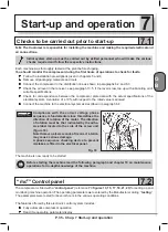
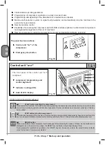
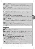


P. 40 - Chap. 7 Start-up and operation
G
B
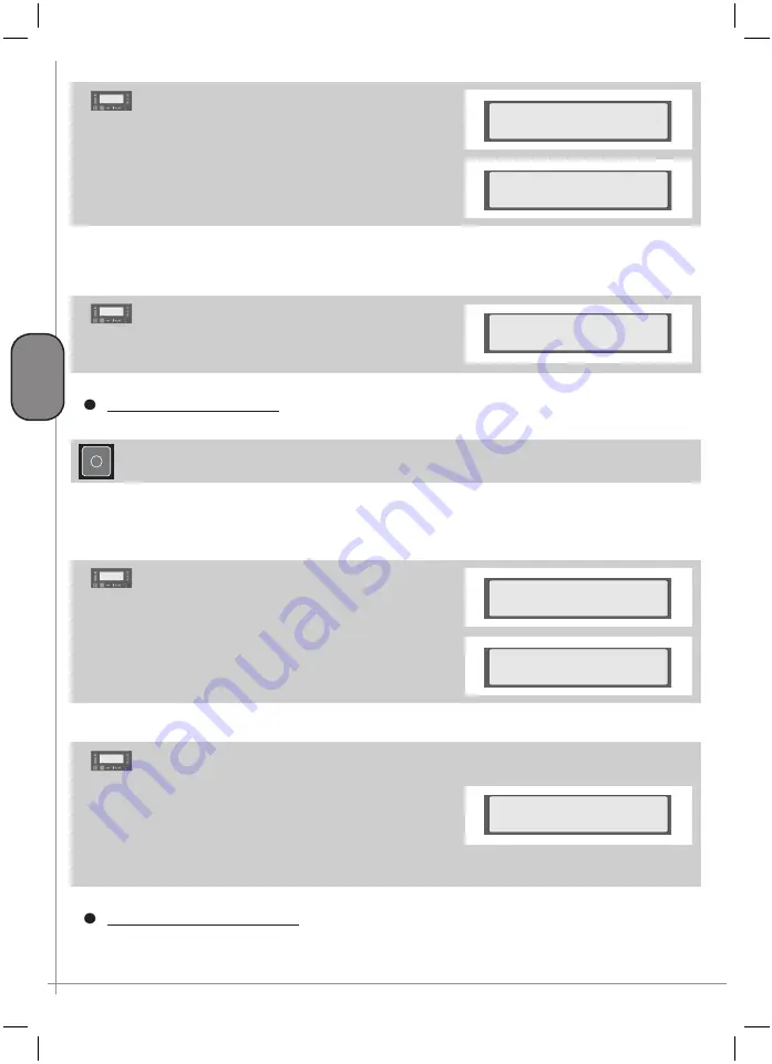
The compressor outputs this message followed by a
countdown.
8
Unload run
hour-date 04m 59s
At the end of the countdown, the compressor switches off,
changing to “Stand-by auto start”, status, ready to restart
in the case of a request for air
Stand by auto start
hour-date
b)
Setting of
CONTIN
. functioning
(see paragraph 7.4.2.3):
The compressor outputs the “
Unload run
” message,
the machine never stops, always remaining available to
restart production of compressed air immediately in the
case of any request.
9
Unload run
hour-date
STOPPING the compressor
Machine starting and stopping is timed.
Simply press the
K2 button to stop
the compressor
The compressor does not stop immediately but initiates a set of operations to stop the machine according to
operating conditions when the STOP command is invoked.
If, at the time of the STOP command, the compressor was operating at full load, the control unit sets the
machine to
unload run
.
Display DI shows this countdown; at the end of the
countdown, the motor is stopped.
10
Stop in XXX sec.
hour-date
At this point, the display shows this additional timing:
during this phase, the compressor vents the pressure
inside the separator reservoir preparing for subsequent
restart.
Blowdown in XXX sec.
hour-date
If the K1-START key is pressed again before the
preset timed restart time has passed, a new timing
is shown on display D1 which indicates the time to
compressor restart
This function prevents restarting the compressor
when it is still pressurized, avoiding electrical motor
verload.
Start in XXX sec.
hour-date
11
Compressor emergency STOP
Press the PE red EMERGENCY STOP button to stop instantaneously the compressor in a hazardous
situation
Содержание FORMULA Series
Страница 1: ...GENESIS FORMULA MODULO 5 5 15 kW USE AND MAINTENANCE HANDBOOK GB ...
Страница 2: ......
Страница 11: ...IX FORMULA 15 kW BA 69 Fig 17 Fig 18 PC PE SPA CF FA PF CT TRL VR BF PS ES EV FU MA RA RO MP PP VA FO FO VS SS ...
Страница 12: ...X MODULO 5 5 7 5 kW Fig 19 Fig 20 FO FD FA SS ES FU MA RA RO PP MP PC PE SCE SF VA EV BF VT TRL CT PF VS PS ...
Страница 14: ...XII MODULO 15 kW BA 69 Fig 23 Fig 24 PS PP PF MA FU RA RO ES VA FO FD VS SS MP CF FA SCE PE PC TRL VR BF CT EV ...
Страница 82: ...P 80 Chap 12 Diagrams G B 12 Diagrams Hydraulic pneumatic plant diagram 12 1 ...
Страница 84: ...P 82 Chap 12 Diagrams G B Power circuit wiring diagram 5 5 15 kW Machines without air dryer 12 2 ...
Страница 85: ...P 83 Chap 12 Diagrams G B Power circuit wiring diagram 5 5 15 kW Machines with air dryer 12 3 ...
Страница 86: ...P 84 Chap 12 Diagrams G B Power circuit wiring diagram 11 kW Machines with inverter 12 4 ...
Страница 87: ...P 85 Chap 12 Diagrams G B Auxiliary circuit wiring diagram 5 5 15 kW Machines without air dryer 12 5 ...
Страница 88: ...P 86 Chap 12 Diagrams G B Auxiliary circuit wiring diagram 5 5 15 kW Machines with air dryer 12 6 ...
Страница 89: ...P 87 Chap 12 Diagrams G B Auxiliary circuit wiring diagram 11 kW Machines with inverter 12 7 ...
Страница 90: ...P 88 Chap 12 Diagrams G B Wiring diagram for component location 5 5 15 kW Machines without air dryer 12 8 ...
Страница 91: ...P 89 Chap 12 Diagrams G B Wiring diagram for component location 5 5 15 kW Machines with air dryer 12 9 ...


