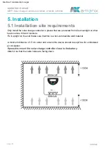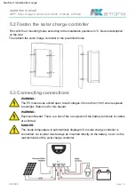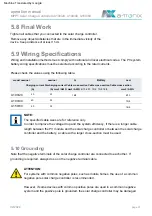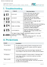
5.6 Connecting the battery
5.7 Connecting the PV module
5.5 Connect load
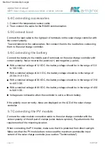
5.4 Connecting accessories
operation manual
02/2022
page 20
Voltages are noticeable when the controller is set to a lithium battery.
With a nominal voltage of 12 VDC, the battery voltage should be in the range of 5.0
to 15.5 VDC.
When connecting the PV module, make sure that it is protected from direct sunlight.
Make sure that the PV module does not exceed the maximum permissible input
current of the solar charge controller (see section "Technical data").
Connect the load cable to the right pair of terminals on the solar charge controller with
the correct polarity.
If the polarity is set correctly, these are displayed on the LCD of the solar charge
controller.
With a nominal voltage of 24 V DC, the battery voltage should be in the range of
20.0 to 31.0 V DC.
To avoid tension in the cables/wires, first connect them to the load before connecting
them to the solar charge controller.
1. Connect the temperature sensor cable.
With a nominal voltage of 36 VDC, the battery voltage should be in the range of 31.0
to 42.0 VDC.
Connect the solar module connection cable to the solar charge controller with the
correct polarity of the left pair of clamps (solar module symbol). Pay attention to the
requirements of the mounting location.
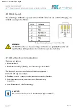
2. Then connect the cable for the RS485 communication.
With a nominal voltage of 48 VDC, the battery voltage should be in the range of 40.0
to 62.0 VDC.
Connect the battery to the middle pair of terminals on the solar charge controller with
correct polarity. Never reverse the positive (+) and negative (-) poles.
MPPT Solar Charge Controllers A100/20, A100/40, A150/60
Machine Translated by Google

