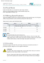
5.10 Grounding
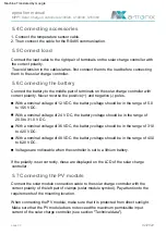
5.9 Wiring Specifications
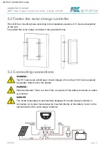
5.8 Final Work
operation manual
Charging current Discharging current Cable cross-section Cable cross-section Cable cross-section
model nominal
(A)
(A) mm2 /AWG mm2 /AWG 6/10 6/10 10/8 10/8 16/5
16/5
nominal
mm2 /AWG
6/10
10/8
16/5
PV
Last
Battery
02/2022
page 21
In order to improve the voltage drop and the system efficiency, if there is a longer cable
length between the PV module and the solar charge controller or between the solar charge
controller and the battery, a cable with a larger cross-section must be used.
30
Please check the values using the following table:
20
NOTE:
The specified cable sizes are for reference only.
20
30
60
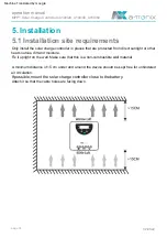
Remove any objects/obstacles that are in the immediate vicinity of the
ATTENTION:
For systems with common negative poles, such as mobile homes, the use of a common
negative pole solar charge controller is recommended.
device. Keep a distance of at least 15 cm.
Tighten all cables that you connected to the solar charge controller.
40
Note that the negative terminals of the solar charge controller are connected to each other. If
grounding is required, always do so on the negative terminal cable.
A100/40
Wiring and installation methods must comply with national and local electrical codes. The PV system
battery wiring specifications must be selected according to the rated currents.
A150/60
A100/20
However, if some devices with common positive poles are used in a common negative
system and the positive pole is grounded, the solar charge controller may be damaged.
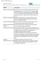
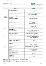
MPPT Solar Charge Controllers A100/20, A100/40, A150/60
Machine Translated by Google

