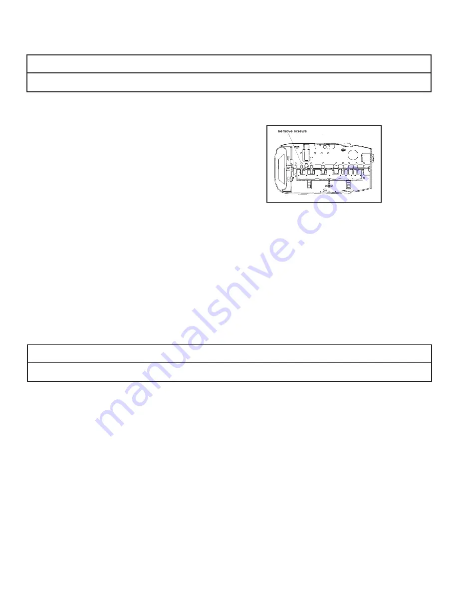
TOP PLATE
The top plate holds the valve discs in place during operation. This plate is removed to allow cleaning and replacing the valve discs.
IMPORTANT NOTE
The valve discs are made from a chloramine resistant severe service rubber. The valve discs will usually not need to be changed. Before removing the top plate
for valve disc service be certain that one of the discs is not operating correctly.
To remove top plate:
1) Disconnect power to unit.
2) Remove cover.
3) Remove motor.
4) Remove camshaft.
5) Place unit in bypass.
6) Release water pressure by pushing the last valve disc open with a screwdriver.
7) Any optional items may be removed.
8) Wiring harnesses should be removed.
9) Remove valve disc spring.
10) Use a Phillips screwdriver to remove the screws from the top plate.
11) Lift the top plate off. All the valve discs can be pulled straight out.
Inspect valve discs for wear. The sealing surface is the raised ridge on the underside of the top shoulder.
Check each valve disc cavity in the valve for debris. Remove any foreign objects before replacing the valve disc.
To install valve discs:
NOTE: If the valve disc fi ts properly in the cavity, it will work correctly.
1) Put the valve disc into the correct (based on shoulder size) valve port cavity. The metal end without rubber coating should be visible.
2) Push down on the shoulder to position the valve disc completely into the port cavity.
The metal portion will be positioned straight up and the top of the shoulder will be level with the valve.
To install the top plate:
NOTE: All valve discs should be in position. Use the same screws that were removed to reassemble the top plate.
IMPORTANT NOTE
Follow the procedure to engage the screws with the existing threads. If the same threads are not used, the holding power of the screw is lost. Under pressure
the valve can leak. Screws that have the same diameter but have different threads should not be used.
1) Position the top plate on top of the valve and over the valve discs.
2) Insert a screw at one of the corner positions.
IMPORTANT: This procedure for reinserting screws must be followed to ensure proper holding strength of the screws.
A. Drop screw of same size and thread into the hole.
B. Use a Phillips screwdriver and lightly rotate the screw backwards
C. When the thread of the screw and thread of the hole match, the screw will “click” and slightly drop down.
D. The threads are lines up. Lightly rotate the screw to tighten and engage threads.
E. Once the threads have engaged the screw can be tightened. Minimal resistance will be present as the screw is turned in. Resistance indicates new threads
are being formed. Back the screw out and rematch the threads.
3) Turn the screw in but do not tighten.
4) Place a second screw into the hole diagonally opposite the fi rst screw and turn in but do not tighten.
5) Insert another screw into one of the remaining corners and turn it in.
6) The fourth screw goes into the hole diagonally opposite. Turn it in.
7) Put the remaining screws in following the same crisscross pattern working from the ends toward the center. When all the screws are in place they can be
tightened down.
8) Start at the corner of the screw pattern and tighten that screw. Work the same pattern from the ends toward the center and crisscrossing as each screw is
tightened. Check that each valve disc moves smoothly before replacing the spring and camshaft.
9) Replace spring.
4-6
Figure 36


