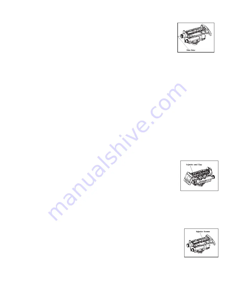
WATER METER MAINTENANCE
Demand Systems
The valve metering devices are used with the demand controls, and may require simple maintenance. In rare instances, the
turbine wheel of the water meter can collect small particles of oxidized iron, eventually preventing the wheel from turning.
1) Shut off the water supply or put the bypass valve(s) into the bypass position.
2) Relieve pressure by opening the backwash drain valve (the seventh back from the controller) with a screwdriver.
3) Loosen and remove the pipe/tube adapters or bypass from the inlet and outlet of the valve body.
4) Using a needle-nose pliers, remove the turbine from the outlet housing. Grasp one of the four vanes of the outer gland and
pull straight out to remove turbine assembly from the outlet of the valve.
5) Carefully remove the turbine wheel from the housing. Use a toothbrush to lightly scrub debris or iron off the magnet. Iron build-up on the surfaces can be reduced
by soaking the wheel in mild sodium hydrosulfi te solution for a few minutes. Flush thoroughly with water.
6) Carefully reinstall the turbine wheel into the turbine cage housing. Make sure that the shaft of the wheel seats into the bearing of the cage. Reassemble the
turbine cage and check that the wheel rotates freely.
7) Reinstall the turbine cage into the outlet of the valve.
8) Reinstall the pipe/tube adapters or bypass to the inlet and outlet of the valve.
9) Turn on the water supply or put the bypass valve(s) into the service position and purge the air out of the system.
10) The system will require the startup procedure to be performed in order to operate appropriately.
CHECK TURBINE OPERATION
After the turbine has been cleaned, verify that the turbine is accurately working. Repressurize the conditioner system, and verify that the controller is plugged in.
Completely turn on a faucet that is plumbed after the conditioning system. After a few seconds, the display should be fl ashing a small faucet icon with water drops.
If this is fl ashing, the turbine is operating properly.
If the faucet icon does not fl ash, then the system may have a faulty turbine probe cable wire harness. Replace that harness and repeat the steps above for checking
for turbine operation.
REFILL FLOW CONTROL
If the brine tank is not refi lling correctly (too much or too little water) the refi ll fl ow control should be cleaned and inspected.
To clean the refi ll fl ow control:
1) Place unit in bypass. Relieve water pressure by pushing open one of the last two valve discs.
2) Remove cap.
3) Pull refi ll fl ow control parts out.
4) Inspect parts for damage.
5) Flush with water and clean with soft brush.
6) Replace refi ll fl ow control parts.
7) Replace cap (hand tight).
DRAIN FLOW CONTROL
If the unit is not supplying conditioned water for as long as when it was fi rst setup, then the drain fl ow control should be cleaned.
To clean the drain fl ow control:
1) Place unit in bypass. Relieve water pressure by pushing open one of the last two valve discs.
2) Remove the drain fl ow control and ball.
3) Inspect parts for damage.
4) Flush with water and clean with soft brush.
5) Orifi ce should be open not plugged.
6) Replace ball and drain fl ow control (hand tight).
4-8
Figure 39
Figure 40
Figure 41


