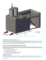
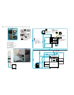

Air
Pressure
Air
Inlet
Nitrogen
Inlet
Nitrogen
Pressure
Coolant
Inlet
Coolant
Outlet
Pneumatics Panel
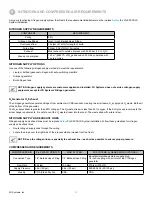
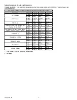
Nitrogen Options
N
2
CDA
min 16° C (60° F)
27° C (80° F)
max
Bulk nitrogen tank
▪ 99% pure nitrogen
▪ option for high nitrogen demand sites
Nitrogen dewars
▪ 99% pure nitrogen
▪ connect dewars with auto-switching
manifold(s) to ensure constant N
2
supply during build
Nitrogen generator
▪ 99% pure nitrogen
Coolant Hoses
▪ Included with 3D Systems-supplied chiller
▪ 1/2" barbed hose fitting
CDA (Clean Dry Air) Inlet
▪ 1/4" barbed hose fitting
Nitrogen Inlet
▪ 1/4" barbed hose fitting
1
2
3
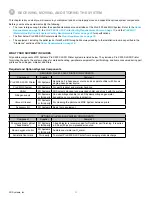
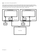
Air Conditioning
• required
•
d
o not install vent directly above process station
Room temperature
setpoint and stability
• set temperature between
18° C and 24° C (65° F and 75° F)
• temperature should be constant to
±
2° C (± 5° F)
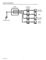
Chiller power panel
• single phase
• separate from process
station power
Process station power panel
• Input: 208VAC, 50/60Hz, 3PH, 10kVA
• separate from chiller power
Process station power cable
•
drop down from ceiling
•
route through cable gland at top of
process station
•
connect to power distribution panel
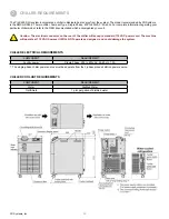
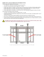
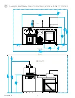
CEILING
Coolant
Access Panel
Pneumatic
Access Panel
Process Chamber
Door
Process Chamber
Panel
Rear Access
Panels
A/C
FRONT
TOP
CHILLER
CHILLER
CHILLER
Room area oxygen monitor
• recommended
• customer supplied/installed
• safety interlock contact rating: 10 A
Transformer
(step-up or step-down)
• customer supplied and installed
• required if facility does not have:
208 VAC, 3-phase
50/60 Hz
10 kVA power
107.1 in 2721 mm
48.3 in 1226 mm
34.5 in 876 mm
21.7 in 550 mm
19.7 in 500 mm
144 in (12 ft )
3658 mm
Coolant Panel
ProX 500 SLS 3D PRINTER FACILITY REQUIREMENTS POSTER
13