ABB VD4 Series, Product Manual
The ABB VD4 Series Instruction Manual is a comprehensive guide for users seeking to maximize the performance of their VD4 circuit breakers. It provides step-by-step instructions and troubleshooting solutions, ensuring hassle-free operation. Download this invaluable resource for free at manualshive.com and enhance your product experience today.
Share
Download


Reviews:
No comments
Related manuals for VD4 Series

DB-75
Brand: Westinghouse Pages: 32

SCO
Brand: ADB Safegate Pages: 30
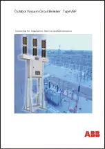
VBF Series
Brand: ABB Pages: 60

XM2 Series
Brand: Alpha Pages: 2

PEBS-S
Brand: Projoy Electric Pages: 2

Pass & Seymour 1594-CMA
Brand: LEGRAND Pages: 2

Vistop 100 A
Brand: LEGRAND Pages: 4

0 897 00
Brand: LEGRAND Pages: 2

Arteor RCBO
Brand: LEGRAND Pages: 4

TX3 RCCBs 4 030 08
Brand: LEGRAND Pages: 9

4 206 59
Brand: LEGRAND Pages: 8

DPX3 250
Brand: LEGRAND Pages: 13

420315
Brand: LEGRAND Pages: 12

DPX3 1600
Brand: LEGRAND Pages: 17

4 149 54
Brand: LEGRAND Pages: 16

4 111 85
Brand: LEGRAND Pages: 26

TX3 6000 A
Brand: LEGRAND Pages: 49


