9
Shape A
(with adapter),
according to ISO 5210 and DIN 3210
Shape B1
(with adapter),
according to ISO 5210
(shape B according to DIN 3210)
Shape B3
(without adapter),
according to ISO 5210
(shape E according to DIN 3210)
Shape D
(without adapter),
according to DIN 3210
Shape C
(without adapter),
according to DIN 3338
The adapters are mounted between the actuator and the valve.
Moreover, the actuators can be delivered with connection according to Russian standards OCT
(connection M, A,
Б, В, Г
),
see the version in table no. 3.
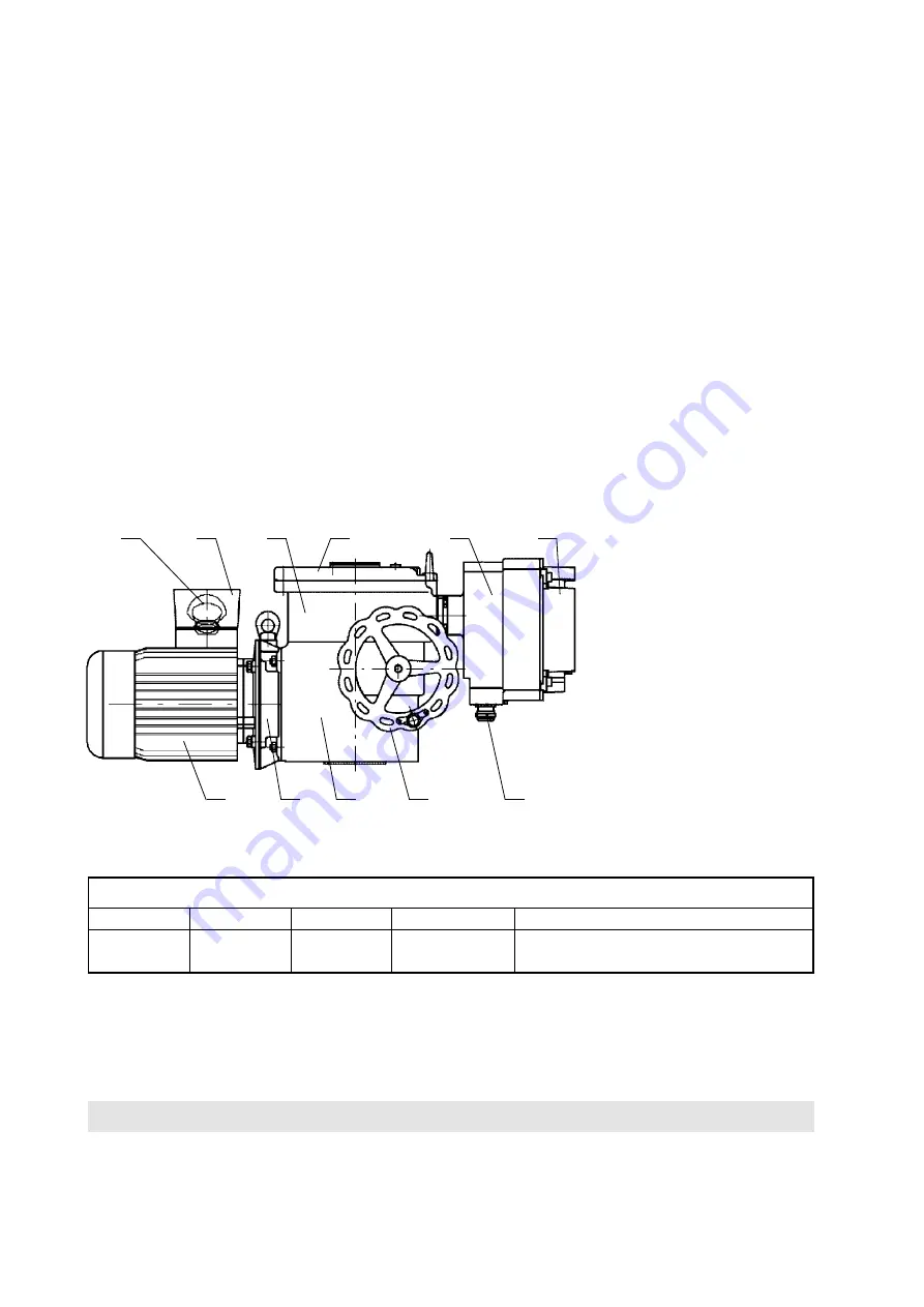
The electric actuator configuration is shown in Fig. 1. The three-phase asynchronous motor 1 drives, via the coun-
tershaft gearing 2, the sun gear of the differential gear unit installed in the actuator supporting box
(power gearing)
3.
In the motor control mode, the crown gear of the planet differential unit is held in fixed position by a self-locking
worm gearing. The handwheel 4 connected with the worm allows manual control even when the motor is running. The
output hollow shaft is fix-connected to the driver of the planet gear and passes to the control box -5- where scanning
and control elements of the actuator are installed.
Operation of the torque-limit switching is derived from axial displacement of the “floating worm” of the manual con-
trol unit which is scanned and transferred to the control box by means of a lever. The control box forms an explosion-
proof closure “d” with designation Ex d IIC T4. The control elements are accessible after removing the cover 6
of this box. Access to the terminal box is possible after removing the cover 8.
The terminal board box also includes a firm closure “d” marked Ex d IIC T4. The cable inlets are secured by certi-
fied cable bushings HAWKE, type ICG 623, with a certificate; they can be used within the temperature range from
-60 °C to +80 °C. The bushings of the following sizes are used in the terminal board box:
cable ø
2 pieces
ICG 623/B
M25x1,5
13,0 – 20,2 mm
Both cliental
2 pieces
ICG 623/A
M20x1,5
11,0 – 14,3 mm
One serves for interconnection with
the electric motor, the other is cliental.
The cable outlet system should meet the requirement of ČSN EN 60079-14 art. 10.3.2.d for direct inlet to the firm
closure of class IIC.
Therefore, in connecting the actuator, the client should provide for a non-explosive sealing
(filling-in individual cable
wires)
by means of the enclosed two-component filling-in putty according to the instructions.
ELECTRONIC OUTFIT
Electro-mechanical control board is replaced with the electronic system
DMS2
or
DMS2 ED.
Both systems
scan position of the output shaft and torque of the electric actuator by contact-free magnetic sensors. Long
service life is guaranteed for the contact-free sensors that do not get mechanically worn.
Description:
1 – three-phase asynchronous motor
2 – countershaft gear box
3 – power gearing
4 – wheel of manual control
5 – control box
6 – control box cover
7 – terminal box
8 – terminal box cover
9 – cable bushings
10 – terminal board
11 – cable bushing for electric motor
Fig. 1 –
Actuator set-up (actuators with DMS2 ED electronic system)
1
2
3
4
9
11
10
5
6
7
8
Summary of Contents for MODACT MO EE 52 120
Page 2: ......
Page 25: ...25 Terminal board of DMS2 Analog Terminal board of DMS2 Profbus...
Page 49: ...NOTES...
Page 50: ...NOTES...


